Small coal mine goaf grouting method based on directional drilling technology

A goaf and directional drilling technology, which is applied in directional drilling, earthwork drilling, mining equipment, etc., can solve the problems of large proportion of invalid drilling, large consumption of steel pipe materials, and waste of drilling costs, etc., to expand coverage and accuracy, avoiding difficult-to-drill areas, and reducing the amount of drilling work

Active Publication Date: 2019-06-07
中煤科工生态环境科技有限公司
View PDF4 Cites 9 Cited by
  • Summary
  • Abstract
  • Description
  • Claims
  • Application Information

AI Technical Summary

Problems solved by technology

[0005] ①Large project volume and high project cost
Since the range of the goaf 2 of the small coal kiln cannot be accurately determined, in order to ensure the treatment effect, more goaf grouting is realized. During the treatment process, the drilling can only be uniformly arranged in an array in the entire area. The spacing is generally 10-25m, which requires large-scale vertical drilling in an area, resulting in a very large overall project volume and high project cost
[0006] ②The proportion of invalid drilling is relatively large
Therefore, there is a large part of invalid vertical boreholes in drilling engineering caused by grouting treatment3
According to the statistics of previous engineering cases, the proportion of invalid drilling is at least as high as 70%, resulting in a large number of drilling projects becoming invalid projects, and at l

Method used


Image

  • Small coal mine goaf grouting method based on directional drilling technology
  • Small coal mine goaf grouting method based on directional drilling technology
  • Small coal mine goaf grouting method based on directional drilling technology

Examples


Embodiment Construction

[0033] The present invention will be described in detail below in conjunction with the accompanying drawings and specific embodiments.

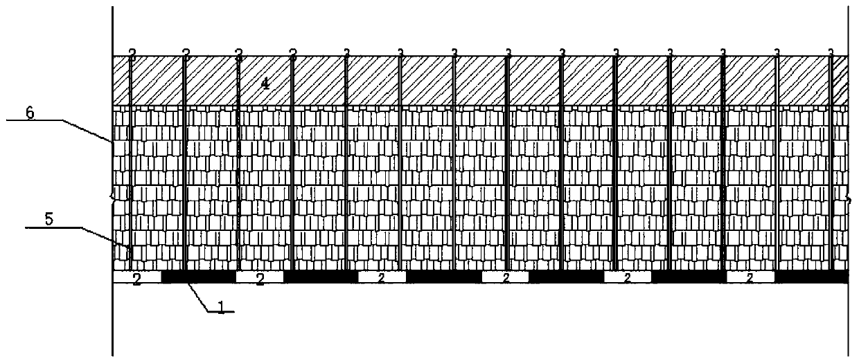
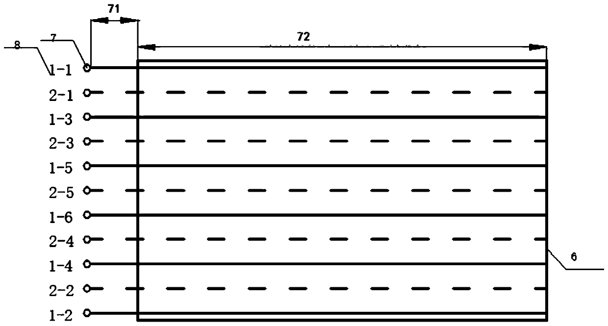
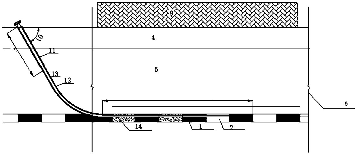
[0034] see figure 2 with image 3 , has shown the small coal kiln goaf grouting method based on directional drilling technology of the present invention, and it specifically implements according to the following steps:

[0035]Step 1, drilling layout, design the layout and quantity of directional drilling in the goaf control area of ​​small coal mines, and determine the parameter design of directional drilling. The layout of directional drilling is carried out according to the transformation of the goaf control area of ​​small coal mines. Among them, for linear projects such as roads, bridges, railways, and high-speed rails that need to be implemented on the goafs of small coal mines, the direction of directional drilling is set as Lay out perpendicular to the direction of the line. For those that need to implement site projects such as da...


PUM


Abstract

The invention provides a small coal mine goaf grouting method based on a directional drilling technology. The advantages of controllable drilling tracks, high goaf disclosing efficiency, high ground adaptability, small drilling work amount, less solid pipe material consumption, low labor strength and the like of the directional drilling technology are fully used for opening up a creatively new path for geological disaster control in a coal mine goaf. The small coal mine goaf grouting method based on the directional drilling technology comprises the steps that a coal seam is horizontally entered through an obliquely straight segment and a deflecting segment, continuous drilling is carried out when coal pillars are encountered in the horizontal drilling process, when the goaf is encountered,a drill rod is recycled, grouting is carried out, after filling grout solidification reaches an another pore-forming condition, hole sweeping is carried out to a previous forming position along an original drilling track, continuous drilling is carried out in solidified man-made geological body, and grouting filling is carried out when entering the goaf again in the forming process. Therefore, the work amount is greatly reduced and the project cost is reduced on the premise of ensuring the grouting control effect of the small coal mine goaf, the innovativeness is greatly achieved, the application range is wide, and market prospects are better.

Description

technical field [0001] The invention relates to the technical field of geological disaster prevention and control in goafs, in particular to a grouting method for goafs in small coal kilns based on directional drilling technology. Background technique [0002] Small coal kiln goaf generally refers to the narrow goaf area formed after coal mine mining, shallow mining depth (mostly within 100m, the deepest can reach 200m~300m), and the plane extension is within 200m. Mined-out areas with branch roadways, irregular or grid-like distribution, mostly unsupported or temporary simple supports. Since the large-scale mining of coal in the 1980s, coal resources have been exploited crazily, forming a large number of gobs in small coal kilns. With the acceleration of urbanization and modernization in my country, the problem of land use for construction has become increasingly prominent. A large number of infrastructure such as roads, railways, bridges, tunnels, reservoir dams, power pl...

Claims


Application Information

Patent Timeline
IPC IPC(8): E21F15/00E21B7/04E21B7/06
Inventor 刘天林刘小平王玉涛张宝元曹晓毅赵文豪白仲荣刘浩琦刘新星田延哲陈超张鑫李珊
Owner 中煤科工生态环境科技有限公司
Why Eureka
Try Eureka