
Metal and carbon fiber reinforced resin matrix composite laminated plate holeless riveting device and method

A technology for reinforcing resin matrix and composite material layer, applied in the field of material processing, can solve the problems of small plasticity and large springback, and achieve the effects of improving plasticity, stable riveting quality and avoiding delamination

Inactive Publication Date: 2019-06-11
YANSHAN UNIV
View PDF5 Cites 3 Cited by
  • Summary
  • Abstract
  • Description
  • Claims
  • Application Information

AI Technical Summary

Problems solved by technology

[0004] Aiming at the problems existing in the prior art, the present invention provides a non-porous riveting device for metal and carbon fiber reinforced resin matrix composite laminates, the purpose of which is to solve the problems of small plasticity and large rebound of carbon fiber reinforced resin matrix composite materials in the stamping process, and the Improve the connection strength of metal / carbon fiber reinforced resin matrix composite laminates due to problems such as delamination and tearing of carbon fiber reinforced resin matrix composites caused by drilling

Method used


Image

  • Metal and carbon fiber reinforced resin matrix composite laminated plate holeless riveting device and method
  • Metal and carbon fiber reinforced resin matrix composite laminated plate holeless riveting device and method
  • Metal and carbon fiber reinforced resin matrix composite laminated plate holeless riveting device and method

Examples


Embodiment Construction

[0023] In order to more clearly illustrate the technical solutions in the embodiments of the present invention or the prior art, the following will briefly introduce the drawings that need to be used in the description of the embodiments or the prior art. Obviously, the accompanying drawings in the following description These are some embodiments of the present invention. For those skilled in the art, other drawings can also be obtained according to these drawings without any creative effort.

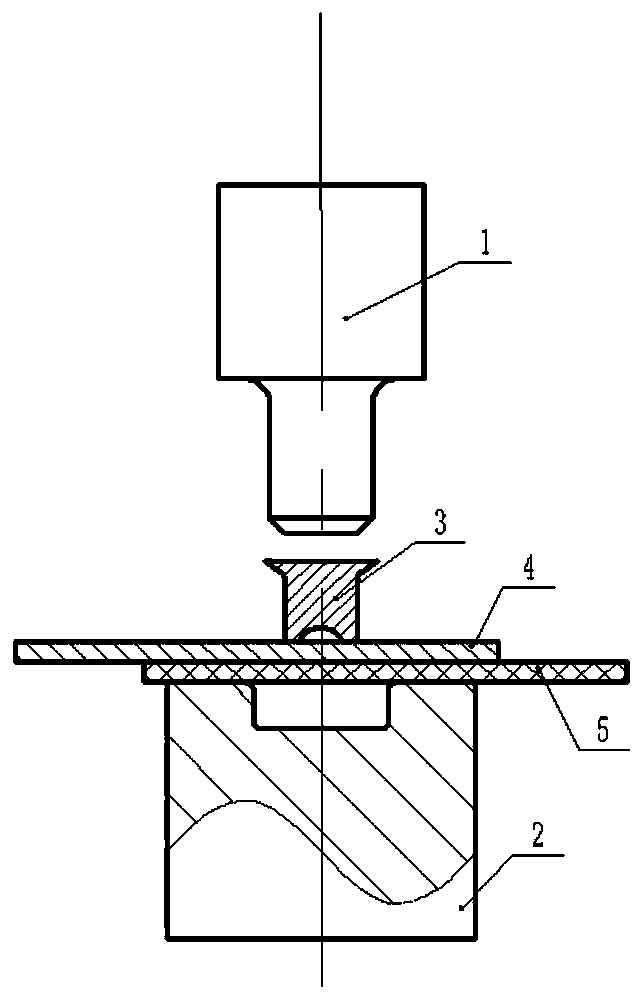
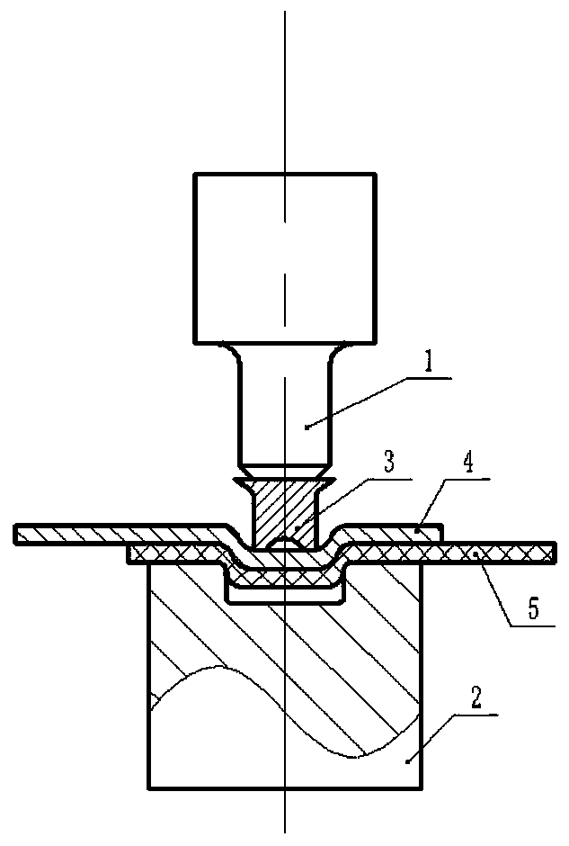
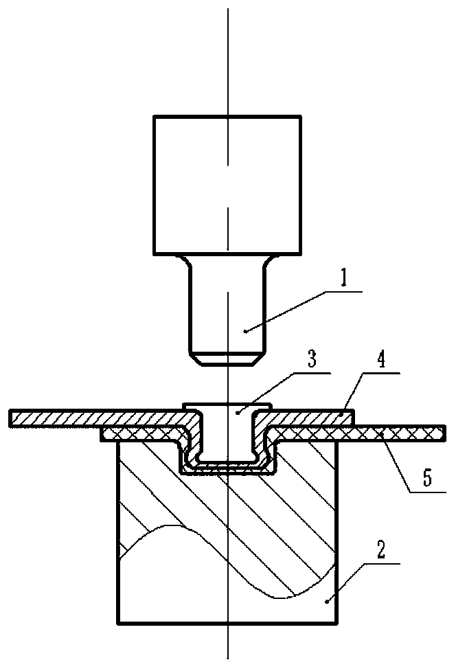
[0024] Such as figure 1 As shown, a non-porous riveting device for metal and carbon fiber reinforced resin matrix composite laminates, including a riveting punch 1, a riveting die 2 and a shallow pit rivet 3, the riveting punch 1 is a cylindrical punch, and the riveting die 2 The cavity is a cylindrical cavity, such as Figure 4 and 5 As shown, the shallow pit rivet 3 has a T-shaped structure, the horizontal section of the shallow pit rivet, that is, the nail cap 31, is in contact wit...


PUM


Abstract

The invention discloses a metal and carbon fiber reinforced resin matrix composite laminated plate holeless riveting device. The riveting device comprises a riveting punch, a riveting female die and ashallow pit rivet. The riveting punch and the riveting female die are connected with a gas-liquid supercharging system. When in a riveting state, the axes of the riveting punch, the riveting female die and the shallow pit rivet coincide. The riveting punch presses the shallow pit rivet into the upper surface of multiple layers of overlapped metal laminated plates and carbon fiber reinforced resinmatrix composite plates. A protrusion is formed on the metal and carbon fiber reinforced resin matrix composite plate under the squeeze effect of the shallow pit rivet. The protrusion is pressed intoa concave cavity of the riveting female die. When the riveting punch returns, the shallow pit rivet stays in the concave cavity of the riveting female die. Through the metal and carbon fiber reinforced resin matrix composite laminated plate holeless riveting device, the problem of buckling deformation of a metal laminated plate is solved; the problems that laminates and carbon fibers of a carbonfiber reinforced resin matrix composite plate strip off and the carbon fibers are twined on a drill bit in the drilling process can also be avoided. Moreover, during connection, a connecting plate part cannot be pierced, and the connecting strength is improved.

Description

technical field [0001] The invention belongs to the technical field of material processing, and in particular relates to a non-porous riveting device and method for laminated plates of metal and carbon fiber reinforced resin matrix composite materials. Background technique [0002] The rivetless connection technology refers to the use of a simple conical punch on the stamping equipment to squeeze the connected plate material into the die with an annular groove at the bottom. Under the action of high pressure, the The sheet material is extruded into the sheet on the die side. During the further extrusion process, the sheet material "flows" plastically, forming a dovetail-shaped inlay, which enables a rivetless connection of the two materials. [0003] The principle of rivetless connection technology is the law of least resistance of metal, that is, metal will first flow to the direction of least resistance when deformed. Therefore, the shape and structure of the mold can be ...

Claims


Application Information

Patent Timeline
Patent Type & Authority Applications(China)
IPC IPC(8): B29C65/60
Inventor 肖宏郑学丰王健芦跃峰
Owner YANSHAN UNIV
Learn More