
Stove heat-insulating shield and stove utilizing stove heat-insulating shield

A technology for heat shields and stoves, which is applied in the field of stoves, and can solve problems such as slippery pans, overflow of cooking soup, swaying combustion flames of gas stoves, and flameout of gas stoves, so as to improve gas utilization, prevent radiation, The effect of increasing capacity

Pending Publication Date: 2019-06-11
NINGBO FOTILE KITCHEN WARE CO LTD
View PDF2 Cites 9 Cited by
  • Summary
  • Abstract
  • Description
  • Claims
  • Application Information

AI Technical Summary

Problems solved by technology

In the actual use of existing gas stoves, since the pot is placed on the pot support for heating, there is a certain space between the pot and the burner. A part escapes into the surrounding environment, causing energy waste; in order to solve the above problems, some heat collection and energy gathering have occurred in China in recent years, such as the "energy gathering ring for gas stoves and gas stoves with it" disclosed in Chinese patent CN203404823U ", and as disclosed in Chinese patent CN204042984U "a kind of energy-gathering gas cooker", the cooker also has an energy-gathering pan support, although the above-mentioned energy-gathering ring structure can reduce the consumption of heat energy to a certain extent, but Gas stoves are generally placed in the ventilated place of the kitchen. When the wind in the external environment is strong, the combustion flame of the gas stove may swing, become unstable, and sometimes even cause flameout, affecting use
In addition, existing ordinary gas stoves still have slippery pots, and cooking soup overflows into the burner burner, fire holes, etc., causing gas stoves to extinguish and fail to ignite.

Method used


Image

  • Stove heat-insulating shield and stove utilizing stove heat-insulating shield
  • Stove heat-insulating shield and stove utilizing stove heat-insulating shield
  • Stove heat-insulating shield and stove utilizing stove heat-insulating shield

Examples


Embodiment 1

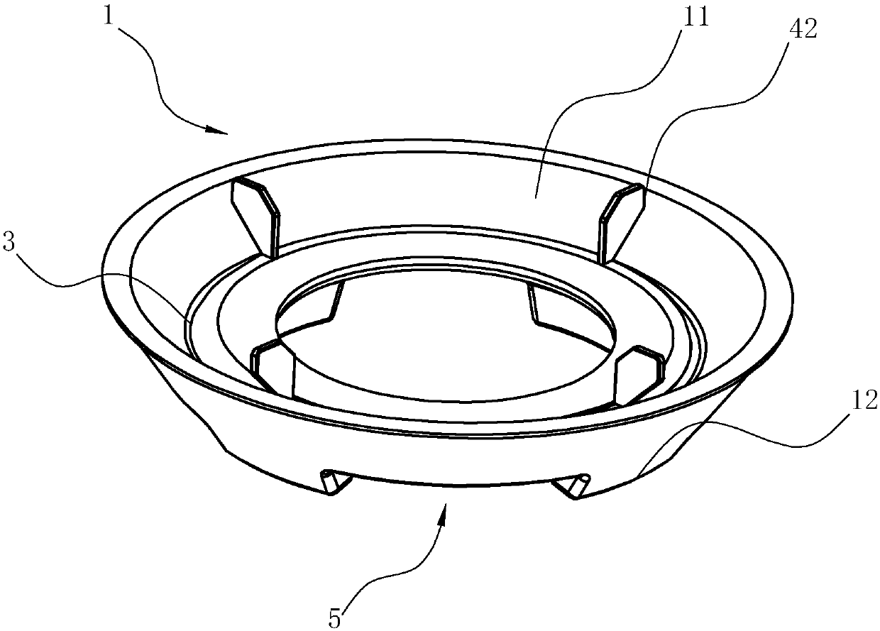
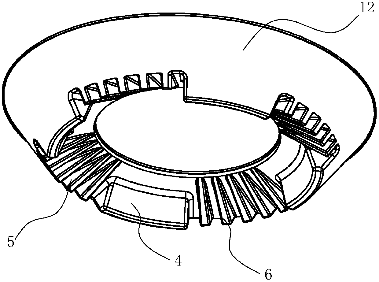
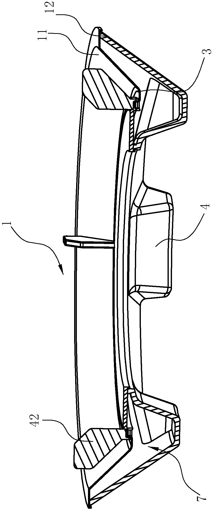
[0024] Such as Figure 1~3 As shown, the stove heat shield in this embodiment includes an annular cover body 1, the cover body 1 is a double-layer structure composed of an upper layer cover 11 and a lower layer cover 12, and there is a gap between the upper layer cover 11 and the lower layer cover 12. Cavity 7, the inside of cavity 7 is filled with air, and the poor heat transfer performance of air is used to play the role of thermal insulation, so as to achieve the purpose of high temperature inside the upper cover 11 and low temperature outside the lower cover 12, thereby achieving a high concentration of heat on the inside and a high degree of heat on the outside. The effect of less heat dissipation, wherein, the lower cover 12 forms the legs 4 by being recessed, causing the legs 4 to also be in a hollow structure. On the one hand, increasing the volume of the cavity of the legs 4 increases the capacity of the air in the cavity, which can effectively reduce the pressure of t...

Embodiment 2

[0030] Such as Figure 5 As shown, the structure is basically the same as that of Embodiment 1, the difference being that the cover body 1 is square.


PUM


Abstract

The invention relates to a stove heat-insulating shield. The shield comprises an annular shield body, and is characterized in that the shield body is of a double-layer structure formed by an upper layer shield and a lower layer shield, a cavity is formed between the upper layer shield and the lower layer shield, pot supporting legs which are arranged at intervals in the circumferential direction are fixed on the upper surface of the upper layer shield. Compared with the prior art, the stove heat-insulating shield has the advantages that the stove heat-insulating shield is additionally arranged, the heat-insulating shield is of a double-layer structure, the heat preservation property is improved, meanwhile, the built-in pot supporting legs are fixedly arranged on the heat-insulating shield,so that heat absorbed by the pot supporting legs can heat the pot bottom as much as possible through heat conduction, meanwhile, the heat loss of flames is reduced. The invention further discloses astove utilizing the heat-insulating shield. Secondary air supplementing grooves of the shield body can be aligned with secondary air inlets of a combustor gas mixing chamber one by one, meanwhile, thesecondary air supplementing grooves of the shield body can be opposite to the secondary air inlets of the combustor gas mixing chamber under the cooperation of a positioning block on a stove panel and a shield body matching groove, so that secondary air can be effectively supplemented.

Description

technical field [0001] The invention relates to a heat shield for a cooker, and also relates to a cooker using the heat shield for a cooker. Background technique [0002] With the development of the city gas industry, my country's stove industry has greatly improved in terms of variety, material, performance, and sales. A very important point in its performance improvement is the improvement of thermal efficiency. The burners of household gas stoves are mostly atmospheric burners. The atmospheric burner is a burner designed according to the partial premixing method, and its primary air coefficient is 0<α<1. The atmospheric burner is divided into two parts: the head and the ejector. The ejector is used to eject the primary air required for combustion, and the function of the burner head is to evenly distribute the mixture of gas and air to the fire hole for stable and complete combustion. The gas of the gas stove is mainly liquefied petroleum gas, natural gas, bioga...

Claims


Application Information

Patent Timeline
IPC IPC(8): F24C15/34
Inventor 郑军妹吴丽波邵海忠王帅东茅忠群诸永定
Owner NINGBO FOTILE KITCHEN WARE CO LTD
Features
  • Generate Ideas
  • Intellectual Property
  • Life Sciences
  • Materials
  • Tech Scout
  • Unparalleled Data Quality
  • Higher Quality Content
  • 60% Fewer Hallucinations
Learn More