High-speed and high-flux particle speed measuring system based on optical time stretching

A time-stretching, high-throughput technology, used in radio wave measurement systems, measurement devices, and re-radiation of electromagnetic waves to achieve the effect of increasing the detection throughput and the upper limit value

Active Publication Date: 2019-06-14
BEIJING UNIV OF CHEM TECH
View PDF7 Cites 4 Cited by
  • Summary
  • Abstract
  • Description
  • Claims
  • Application Information

AI Technical Summary

Problems solved by technology

[0006] In order to overcome the defect that the above-mentioned technology cannot complete the velocity measurement of high-speed and high-throughput particles, the present invention proposes a high-speed and high-throughput particle velocity measurement system based on optical time stretching

Method used


Image

  • High-speed and high-flux particle speed measuring system based on optical time stretching
  • High-speed and high-flux particle speed measuring system based on optical time stretching
  • High-speed and high-flux particle speed measuring system based on optical time stretching

Examples


Embodiment 1

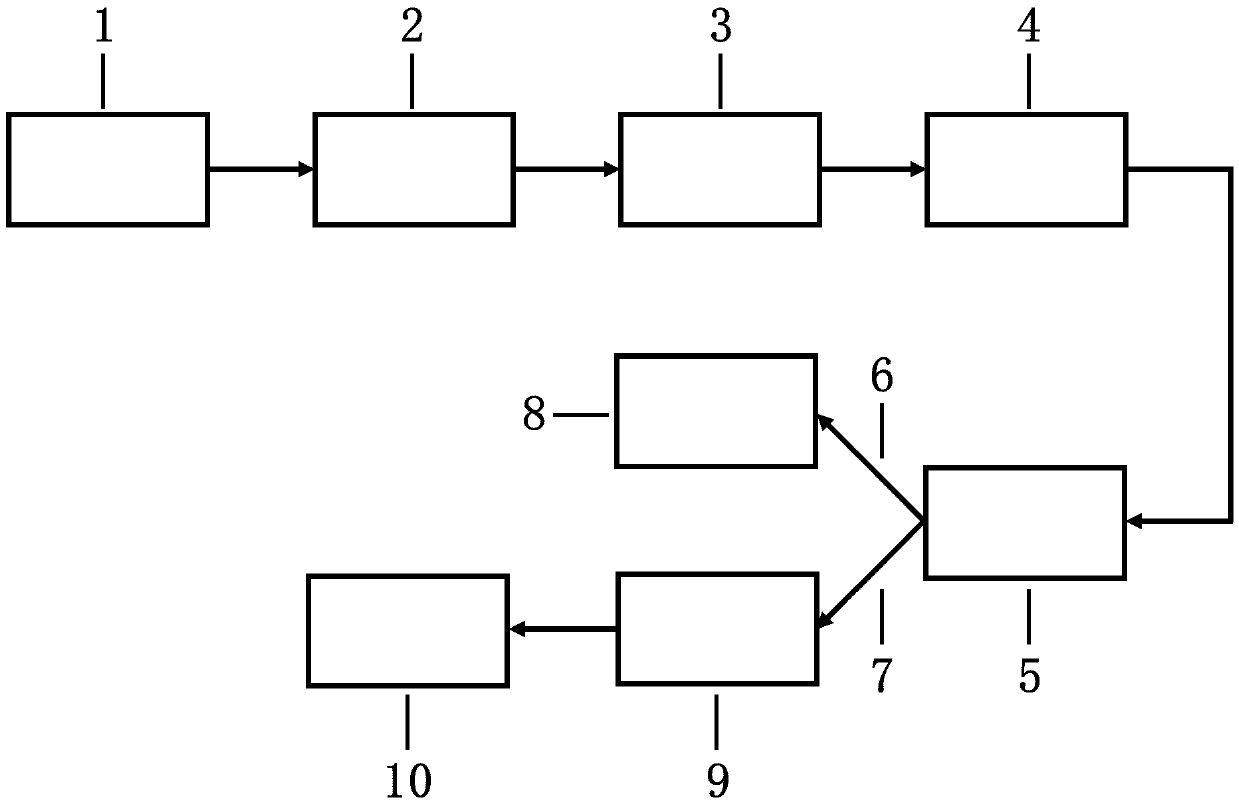
[0036] The center wavelength of the optical pulse output by the light source 1 used in this embodiment is 1560 nm, the bandwidth is 15 nm, and the pulse repetition frequency is 25 MHz.

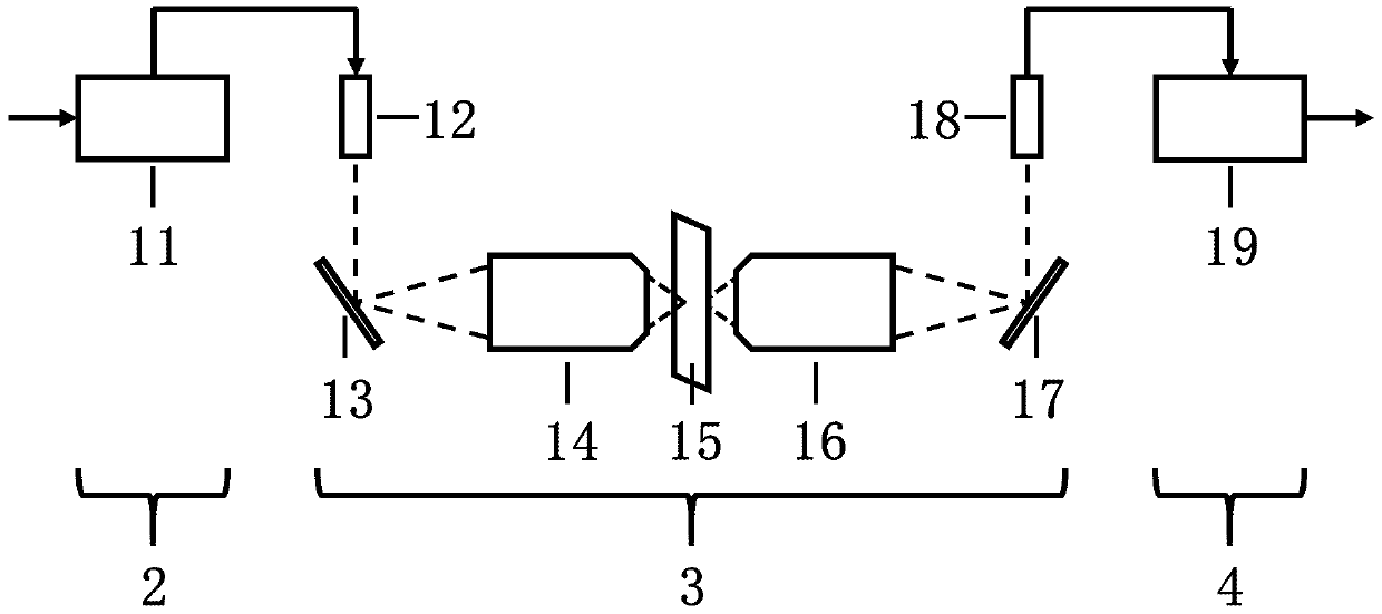
[0037] Such as figure 2 As shown, the time stretching module 2 includes a single-mode dispersion compensating optical fiber 11 with a dispersion of 1200 ps / nm, which is installed at the light output measurement of the light source 1, and is used to map the spectral information of the optical pulse to its time-domain waveform one by one to complete the optical fiber. Time-wavelength mapping of pulses. The space mapping module 3 adopted in this embodiment includes a transmissive space mapping module, which is output to the space by the fiber collimator 12, and enters the first lined diffraction grating 13 with a line density of 1200 lines / mm at an incident angle of 80°. According to the raster formula

[0038]

[0039] where θ 1 is the incident angle of the light pulse, θ 2 is the exit a...

Embodiment 2

[0045] The difference between this embodiment and Embodiment 1 is that the space mapping module 3 used in this embodiment includes a reflective space mapping module.

[0046] Such as Figure 5 As shown, the time stretching module 2 includes a single-mode dispersion compensating optical fiber 11 with a dispersion of 1200 ps / nm, which is installed at the light output measurement of the light source 1, and is used to map the spectral information of the optical pulse to its time-domain waveform one by one to complete the optical fiber. Time-wavelength mapping of pulses. The space mapping module 3 adopted in this embodiment includes a reflective space mapping module, and the optical pulse from the single-mode dispersion compensating fiber 11 is transmitted to the fiber collimator 12 by the fiber circulator 20, and then output to the space by the fiber collimator 12, Incident angle of 80° is incident on the first reticle diffraction grating 13 with a reticle density of 1200lines / mm...


PUM


Abstract

The invention discloses a high-speed and high-flux particle speed measuring system based on optical time stretching. The high-speed and high-flux particle speed measuring system comprises a light source (1), a time stretching module (2), a space mapping module (3), an amplifier (4) and a beam splitter (5) which are sequentially connected, the output end of the beam splitter (5) adopts two-way output and is divided into an upper branch (6) and a lower branch (7), the output upper branch of the beam splitter (5) is connected with a spectrum analyzer (8), and the output lower branch of the beam splitter (5) is connected with a photoelectric detector (9) and a data acquisition processor (10). According to the high-speed and high-flux particle speed measuring system, particle high-speed line scanning is completed through an optical time stretching technology, speed limitation and flux limitation of a conventional particle speed measuring method are broken through, and the speed upper limitand the detection flux of particle speed measuring are increased effectively.

Description

technical field [0001] The invention belongs to the field of optoelectronic technology, and relates to a high-speed and high-flux particle velocity measurement system based on optical time stretching. Background technique [0002] Particle flow velocity detection has important applications in real life, production and scientific research, such as disease detection, internal combustion engine fuel injection control, and particle electrophoretic mobility measurement. Achieving high-speed and high-throughput particle velocity measurement is a key issue and a long-standing challenge. [0003] At present, for particle velocimetry, commonly used techniques include Laser Doppler Velocimetry and Particle Image Velocimetry. Among them, the laser Doppler velocimeter uses the Doppler frequency shift that occurs when the light hits the moving particles to complete the particle velocity measurement. It has been applied to the field of biomedicine for disease detection (M. Stucker, V. Bai...

Claims


Application Information

Patent Timeline
Patent Type & Authority Applications(China)
IPC IPC(8): G01S17/58G01S7/481
Inventor 丁迎春俞力奇冯祺何惠梅邢晓星
Owner BEIJING UNIV OF CHEM TECH
Why Eureka
Try Eureka