Household video monitoring system

A video surveillance system, home technology

Inactive Publication Date: 2019-06-14
冯芊雅
View PDF4 Cites 19 Cited by
  • Summary
  • Abstract
  • Description
  • Claims
  • Application Information

AI Technical Summary

Problems solved by technology

[0002] The network video monitoring system is a system that combines computer IP video technology, video and audio data compression and decompression processing technology, and Internet application technology. The remote video control system can release the monitoring information monitoring center and make it reachable through the computer network. Desktop computer, so as to integrate with information management system and office automation system to better serve management and improve management level and efficiency. The home video surveillance system is designed with this as the core technology, which improves the management of home environment monitoring. level and efficiency, however, the home video surveillance system itself sometimes fails, especially the problem of signal disorder, which leads to errors in the data of the home video surveillance system. It is necessary to detect the signal of the signal transmission channel in the control terminal of the home video surveillance system in real time

Method used


Image

  • Household video monitoring system
  • Household video monitoring system

Examples


Embodiment 1

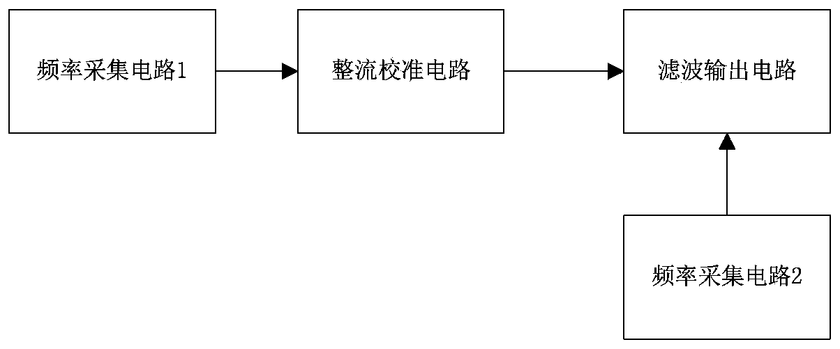
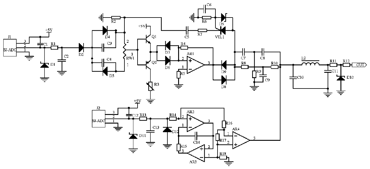
[0014] Embodiment 1, a home video monitoring system, including a frequency acquisition circuit 1, a frequency acquisition circuit 2, a rectification calibration circuit and a filter output circuit, the frequency acquisition circuit 1 and the frequency acquisition circuit 2 respectively collect the frequency in the control terminal of the home video monitoring system Analog signals at both ends of the input and output ends of the signal transmission channel, the signal transmission channel is the channel for the control terminal in the home video surveillance system to receive the analog signal, and the rectification calibration circuit uses variable resistor RW1, capacitor C4, and capacitor C3 to form a rectification circuit For signal rectification, use triode Q1 and triode Q2 to form a push-pull circuit to reduce the conduction loss of the signal, and use diode D6-diode D9 and operational amplifier AR1 to form a composite circuit to limit-amplify-limit the signal, and finally ...

Embodiment 2

[0016] Embodiment 2. On the basis of Embodiment 1, the filter output circuit uses inductor L2, capacitor C10, and capacitor C11 to form a π-type filter circuit to filter and output to filter out signal clutter, that is, to control the home video surveillance system. The compensation signal of the output signal of the signal transmission channel in the terminal is used to reduce the signal error and prevent signal disturbance. One end of the inductor L2 is connected to one end of the capacitor C10 and the output end of the operational amplifier AR4, and the other end of the inductor L2 is connected to the resistor R11, the other end of capacitor C11, capacitor C10, the other end of capacitor C11 is grounded, the other end of resistor R11 is connected to one end of resistor R12 and one end of voltage regulator tube D10, the other end of voltage regulator tube D10 is grounded, and the other end of resistor R12 Connect to the signal output port.

Embodiment 3

[0017]Embodiment three, on the basis of embodiment two, the frequency acquisition circuit 1 and the frequency acquisition circuit 2 select the signal frequency acquisition device J1 and the signal frequency acquisition device J2 of the SJ-ADC model to collect respectively in the control terminal of the home video surveillance system Analog signals at both ends of the signal transmission channel input and output, the signal transmission channel is the channel for the control terminal in the home video surveillance system to receive the analog signal, the frequency acquisition circuit 2 uses op amp AR2-op amp AR4 and capacitor C14 Composing a loss compensation circuit to compensate the output signal of the rectification calibration circuit to further ensure the consistency of the signal, prevent the potential inconsistency between the compensation signal and the source signal, and improve the reliability of the circuit. The power supply terminal of the signal frequency collector J...


PUM


Abstract

The invention discloses a household video monitoring system. The system comprises a frequency acquisition circuit 1, a frequency acquisition circuit 2, a rectification calibration circuit and a filtering output circuit. The frequency acquisition circuit 1 and the frequency acquisition circuit 2 respectively acquire analog signals at the input end and the output end of a signal transmission channelin a control terminal of the household video monitoring system. The rectification calibration circuit uses a variable resistor RW1, a capacitor C4, and a capacitor C3 to form a rectifying circuit torectify the signal, and uses a diode D6-diode D9 and an amplifier AR1 to form a composite circuit for signal limiting, amplification, and limiting processing. The frequency acquisition circuit 2 usesthe op amp AR2-AR4 and the capacitor C14 to form a loss compensation circuit to compensate the output signal of the rectification and calibration circuit. Finally, the filter output circuit uses the inductor L2, the capacitor C10, and the capacitor C11 to form a [pi]-type filter circuit. The filtered output can convert the signal frequency into a compensation signal of the signal at the output endof the signal transmission channel in the control terminal of the home video monitoring system.

Description

technical field [0001] The invention relates to the field of circuit technology, in particular to a home video monitoring system. Background technique [0002] The network video monitoring system is a system that combines computer IP video technology, video and audio data compression and decompression processing technology, and Internet application technology. The remote video control system can release the monitoring information monitoring center and make it reachable through the computer network. Desktop computer, so as to integrate with information management system and office automation system to better serve management and improve management level and efficiency. The home video surveillance system is designed with this as the core technology, which improves the management of home environment monitoring. level and efficiency, however, the home video surveillance system itself sometimes fails, especially the problem of signal disorder, which leads to errors in the data of...

Claims


Application Information

Patent Timeline
Patent Type & Authority Applications(China)
IPC IPC(8): H04N7/18
Inventor 冯芊雅
Owner 冯芊雅
Why Eureka
Try Eureka