
Rotating device with damping device and rotating method of rotating device

A technology of rotating device and damping device, which is applied in the direction of transmission device, transmission device parts, electromechanical device, etc., can solve the problems of unstable shooting picture, mechanical structure shaking can not be suppressed to the greatest extent, lens shaking, etc., to achieve stability and smoothness performance, guaranteed stability, and easy maintenance

Active Publication Date: 2019-06-18
NANJING UNIV OF SCI & TECH +1
View PDF10 Cites 0 Cited by
  • Summary
  • Abstract
  • Description
  • Claims
  • Application Information

AI Technical Summary

Problems solved by technology

[0003] In the movement of the rocker camera robot, the rotation of the rocker arm is an essential part, so the performance of the rotation device of the rocker arm in the rocker camera robot largely determines the quality of the shooting picture, but currently there is no The rotating device with damping device, the rotating device currently on the market is a structural component without a damping device, which is directly driven and controlled by a motor and a reducer. This control method will cause lens shake during actual operation, which will cause shooting The picture is unstable, especially when the robot starts to rotate and stops suddenly.
Based on this phenomenon, in the actual operation process, it is possible to adjust the corresponding operating speed, acceleration and deceleration and other motion parameters by adjusting the position of the camera or improving the control program to perform a certain degree of defibrillation treatment, but the vibration caused by the mechanical structure cannot be maximized. to suppress

Method used


Image

  • Rotating device with damping device and rotating method of rotating device
  • Rotating device with damping device and rotating method of rotating device

Examples


Embodiment 1

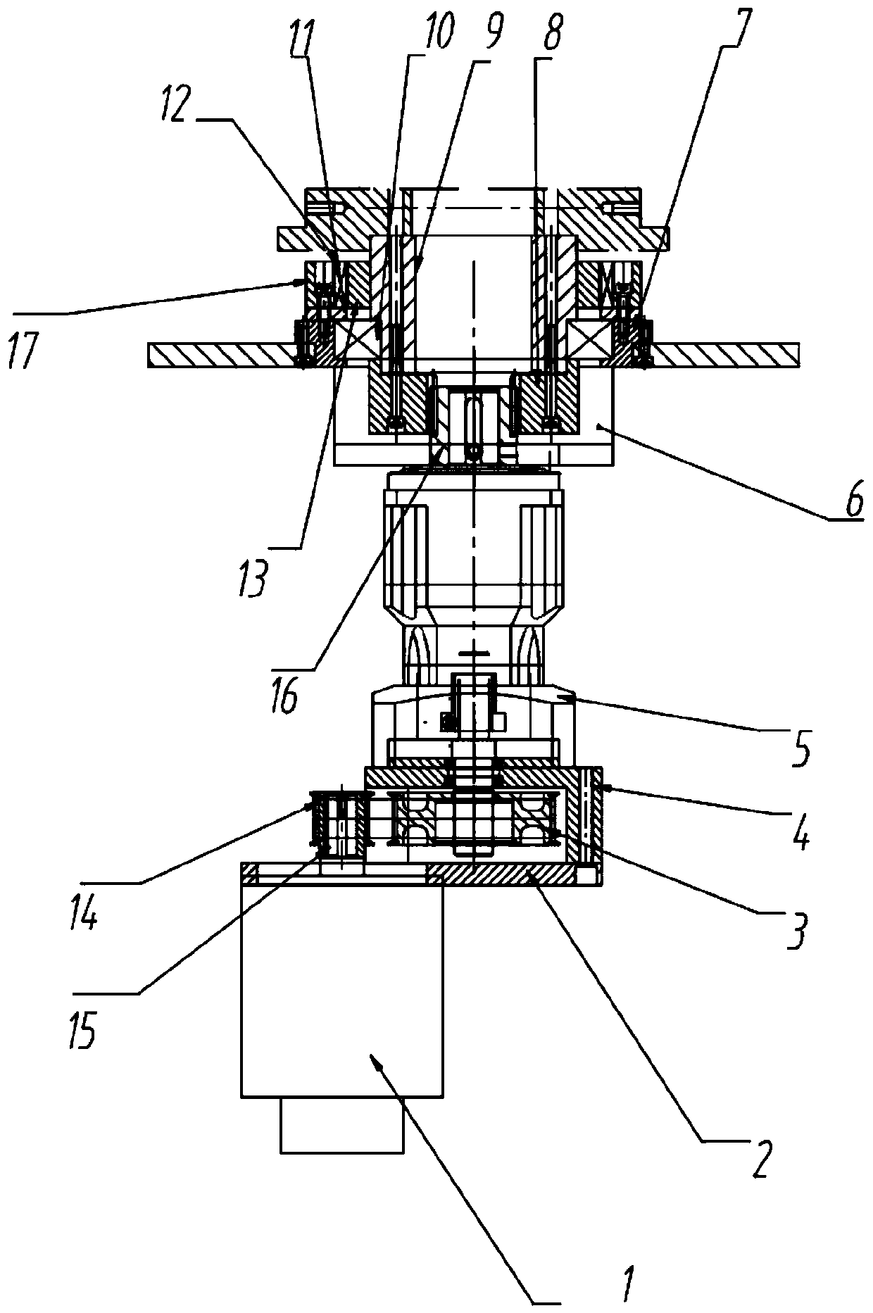
[0036] A rotating device with a damping device, including a transmission mechanism and a damping mechanism, wherein the transmission mechanism includes a servo motor 1, a large pulley 3, a motor pulley 14, a reducer 5, and a connecting hollow shaft 9, and the damping mechanism includes magnetic damping device 17;

[0037] The servo motor 1 is fixedly connected on the motor plate 2, and the motor pulley 14 is arranged on its input shaft 15, and the motor pulley 14 drives the large pulley 3 to rotate; the large pulley 3, the reducer 5 and the connecting empty shaft 9 are arranged coaxially, The large pulley 3 is connected to the reducer 5 fixedly connected to the motor base plate 6 through the reducer interface 4, and the output shaft of the reducer 5 is connected to the end connected to the empty shaft 9 through the large gear 8 for output transmission to drive the connected empty shaft 9 To rotate, the other end connected to the hollow shaft 9 is fixedly connected to the part ...

Embodiment 2

[0040] On the basis of Embodiment 1, a pinion 16 is arranged on the output shaft of the speed reducer 5 , and the pinion 16 meshes with the bull gear 8 .

Embodiment 3

[0042] On the basis of Embodiment 1 or Embodiment 2, the motor pulley 14 and the large pulley 3 are in the same horizontal plane, and the motor pulley 14 drives the large pulley 3 to rotate through the synchronous belt.


PUM


Abstract

The invention discloses a rotating device with a damping device, and belongs to the technical field of camera control devices of rocker-arm photographing robots. The rotating device comprises a transmission mechanism and a damping mechanism, wherein the transmission mechanism comprises a servo motor, a large belt wheel, a motor belt wheel, a speed reducer and a connecting hollow shaft; the dampingmechanism comprises a magnetic damper; input torque of the servo motor is transmitted to the connecting hollow shaft through the motor belt wheel, the large belt wheel and the speed reducer; the connecting hollow shaft drives a to-be-rotated part to move; and in a motion process of the connecting hollow shaft, buffering damping can be realized through the magnetic damper. The rotating device achieves the buffer effect on a damping system, reduces lens shake, caused by vibrations in a rotating process, of a robot rocker arm, and controls integral stability. The rotating device is simple in structure, is easy in assembly, is stable in performance, and can be widely applied to the media industry.

Description

technical field [0001] The invention belongs to the technical field of camera robot lens control, in particular to a rotating device with a damping device and a rotating method thereof. Background technique [0002] The camera rocker can complete long-distance, high-lift, rotating lens and other high-dynamic visual effect lenses in film and television production and shooting. It is often used in movies, TV dramas, promotional films, advertisements, etc. At present, with the price of The continuous decline and the lightness of the rocker arm have also been widely used in small meetings and wedding scenes. With the development of virtual studio technology, rocker camera robots have gradually been favored by the majority of TV stations. [0003] In the movement of the rocker camera robot, the rotation of the rocker arm is an essential part, so the performance of the rotation device of the rocker arm in the rocker camera robot largely determines the quality of the shooting pict...

Claims


Application Information

Patent Timeline
Patent Type & Authority Applications(China)
IPC IPC(8): F16H57/00F16H37/02F16F15/03F16M11/06F16M11/18F16M11/20G03B17/56H02K7/10
CPCY02E10/72
Inventor 欧屹谢志坤黄俊朋潘东倩
Owner NANJING UNIV OF SCI & TECH
Learn More