
Chamber environment recovery method and etching method

A recovery method and chamber technology, applied in the direction of discharge tubes, electrical components, circuits, etc., can solve the problems of reduced etching rate, reduced ion density, and contamination of wafers, so as to inhibit shedding, prevent particle shedding, and solve particle pollution Effect

Active Publication Date: 2021-08-13
BEIJING NAURA MICROELECTRONICS EQUIP CO LTD
View PDF7 Cites 0 Cited by
  • Summary
  • Abstract
  • Description
  • Claims
  • Application Information

AI Technical Summary

Problems solved by technology

If the deposited carbonaceous material reaches a certain thickness, the particles will become loose and fall off, contaminating the wafer
For this reason, in the prior art, usually adopt the following method: after etching a certain amount (50 or 100) of wafers, it is often necessary to carry out an oxygen treatment process: feed a certain amount of oxygen into the chamber, and be excited Oxygen plasma is generated, and the particles of carbonaceous materials are oxidized to produce carbon oxides (CO / CO 2 ), and then pumped away by the molecular pump, so as to achieve the purpose of inhibiting the growth and shedding of particles; however, after the oxygen treatment process is completed, oxygen or by-products containing oxygen will remain in the chamber, which will cause further etching. The reduction of ion density is reflected in the result that the etching rate is reduced, and the general decline is 40% to 50%. For this reason, the prior art usually etches silicon dioxide SiO2 after the oxygen treatment process. 2 process to restore the chamber environment to ensure the etching rate, but this process generally takes 10 to 20 minutes to carry out the normal process, which greatly reduces the production capacity

Method used


Image

  • Chamber environment recovery method and etching method
  • Chamber environment recovery method and etching method
  • Chamber environment recovery method and etching method

Examples


Embodiment Construction

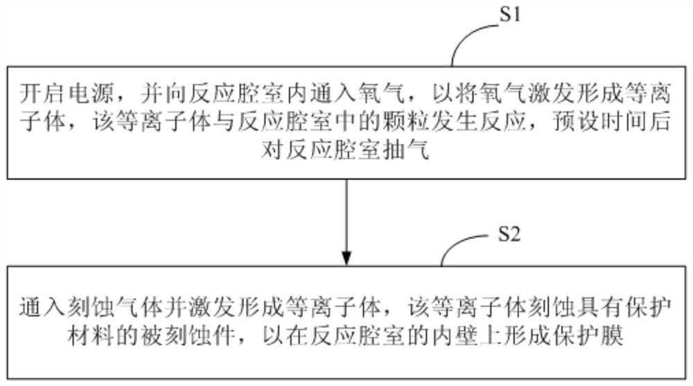
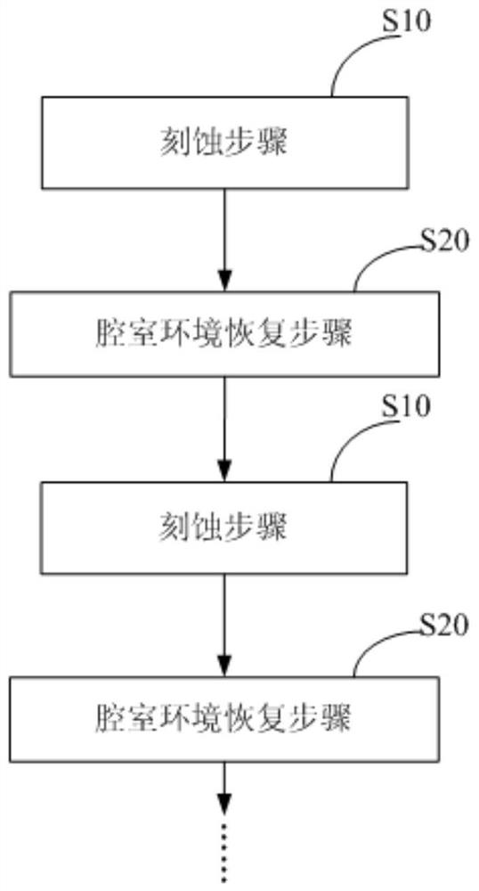
[0029] In order for those skilled in the art to better understand the technical solutions of the present invention, the chamber environment restoration method and the etching method provided by the present invention will be described in detail below in conjunction with the accompanying drawings.

[0030] figure 2 It is a flow chart of the chamber environment restoration method provided in the first embodiment of the present invention, image 3 It is a flow chart of the etching method provided by the second embodiment of the present invention. see image 3 The etching method provided by the second embodiment of the present invention includes alternately performing the etching step S10 and the chamber environment restoration step S20, wherein the chamber environment restoration step S20 adopts the chamber environment restoration method provided in the following embodiments of the present invention, The etching step may include, but is not limited to: continuously etching a pr...


PUM


Abstract

The invention provides a chamber environment recovery method, comprising: an oxidation step: turning on the power supply, and introducing oxygen into the reaction chamber, so as to excite the oxygen to form plasma, and the plasma reacts with the particles in the reaction chamber to pre- Evacuate the reaction chamber after a certain period of time; protective film forming step: feed the etching gas and excite to form a plasma, which etches the etched piece with the protective material to form on the inner wall of the reaction chamber Forms a protective film. The present invention also provides an etching method. The chamber environment recovery method and the etching method can not only solve the particle pollution, but also ensure the productivity and the etching rate of the subsequent etching process at the same time.

Description

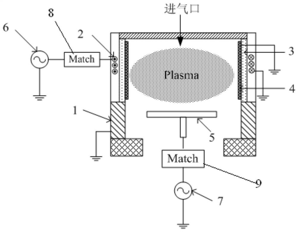
technical field [0001] The invention belongs to the technical field of microelectronic processing, and in particular relates to a chamber environment restoration method. Background technique [0002] In physical vapor deposition (PVD) semiconductor process equipment, an inductively coupled (ICP) plasma generator is usually used as a precleaning (Preclean) chamber, the purpose of which is to remove contamination and impurities on the wafer surface before the process, which is beneficial to The effective implementation of the subsequent etching process ensures the integration of integrated circuits and device performance. [0003] figure 1 For a schematic diagram of an existing preclean chamber, see figure 1 , the pre-cleaning chamber includes a cavity 1, an induction coil 2, a ceramic bucket 3, a Faraday shield 4, a base 5 for placing a wafer, an upper electrode RF power supply 6, and a lower electrode RF power supply 7. Among them, the base 5 is set in the cavity 1; the F...

Claims


Application Information

Patent Timeline
Patent Type & Authority Patents(China)
IPC IPC(8): H01J37/32H01L21/3065
CPCH01J37/32H01L21/00H01L21/3065
Inventor 徐奎侯珏陈鹏
Owner BEIJING NAURA MICROELECTRONICS EQUIP CO LTD
Learn More