

A New Preparation Technology of Thermal Barrier Coating
A technology of thermal barrier coating and preparation process, which is used in metal material coating process, coating, melt spraying and other directions
- Summary
- Abstract
- Description
- Claims
- Application Information
AI Technical Summary
Problems solved by technology
Method used
Image

Examples
Embodiment 1
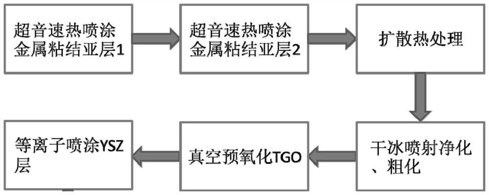
[0051] Step 1. Generate a composite metal bond primer on the surface of the substrate. Specifically include:
[0052] Step 11. Prepare a first metal bonding primer layer of about 50 μm on the surface of the substrate by a supersonic flame spraying process.
[0053] Step 12. Prepare a second metal bonding primer layer of about 50 μm on the surface of the substrate by a supersonic flame spraying process.
[0054] Both the first metal bond primer and the second metal bond primer were made of MCrAlY powder. The second metallic bond primer has a greater aluminum content than the first metallic bond primer.
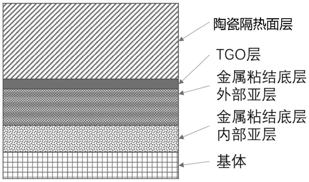
[0055] Step 13. Vacuum diffusion heat treatment. Interdiffusion occurs between the first metal bonding primer and the second metal bonding primer, forming a layer on the surface consisting of an outer sublayer that is relatively aluminum-rich and has a higher elastic modulus and an inner layer that is relatively chromium-rich and has a lower elastic modulus Composite metal ...
Embodiment 2
[0061] Step 1. Generate a composite metal bond primer on the surface of the substrate. Specifically include:
[0062] Step 11. Prepare a first metal bonding primer layer with a thickness of about 100 μm on the surface of the substrate by a supersonic flame spraying process.
[0063] Step 12. Prepare a second metal bonding primer with a thickness of about 100 μm on the surface of the substrate by a supersonic flame spraying process.
[0064] Both the first metal bond primer and the second metal bond primer were made of MCrAlY powder. The second metallic bond primer has a greater aluminum content than the first metallic bond primer.
[0065] Step 13. Vacuum diffusion heat treatment. Interdiffusion occurs between the first metal bonding primer and the second metal bonding primer, forming a layer on the surface consisting of an outer sublayer that is relatively aluminum-rich and has a higher elastic modulus and an inner layer that is relatively chromium-rich and has a lower ela...
Embodiment 3
[0071] Step 1. Generate a composite metal bond primer on the surface of the substrate. Specifically include:
[0072] Step 11. Prepare a first metal bonding primer layer with a thickness of about 150 μm on the surface of the substrate by a supersonic flame spraying process.
[0073] Step 12. Prepare a second metal bonding primer with a thickness of about 150 μm on the surface of the substrate by a supersonic flame spraying process.
[0074] Both the first metal bond primer and the second metal bond primer were made of MCrAlY powder. The second metallic bond primer has a greater aluminum content than the first metallic bond primer.
[0075] Step 13. Vacuum diffusion heat treatment. Interdiffusion occurs between the first metal bonding primer and the second metal bonding primer, forming a layer on the surface consisting of an outer sublayer that is relatively aluminum-rich and has a higher elastic modulus and an inner layer that is relatively chromium-rich and has a lower ela...
PUM
| Property | Measurement | Unit |
|---|---|---|
| thickness | aaaaa | aaaaa |
| sublimation point | aaaaa | aaaaa |
| thickness | aaaaa | aaaaa |
Abstract
Description
Claims
Application Information