
Device for generating arbitrary frequency multiplication signals of optical frequency combs on basis of coupled type optoelectronic oscillator

A technology for generating devices and frequency-multiplied signals, applied in optical demodulation, optical waveguide coupling, optics, etc., can solve problems such as poor flatness, introduction, and large carrier noise

Active Publication Date: 2019-06-25
ZHEJIANG UNIV
View PDF6 Cites 2 Cited by
  • Summary
  • Abstract
  • Description
  • Claims
  • Application Information

AI Technical Summary

Problems solved by technology

[0003] In order to produce an optical frequency comb with low phase noise, high stability, and adjustable frequency, researchers have made arduous explorations. At first, researchers used the mode-locked laser method, that is, the relative phase of each longitudinal mode in the mode-locked laser that satisfies the start-up condition Locked in a certain way, the coherent superposition in the time domain forms a strong and periodic ultrashort pulse sequence, and in the frequency domain it is an optical frequency comb with a fixed interval; although the structure of this method is relatively simple, the carrier The number is large, but there are disadvantages that the number of optical carriers is not easy to control and the flatness is poor
In order to improve the flatness of the optical frequency comb, researchers have invented the cyclic frequency shift method. There are many schemes to generate the optical frequency comb based on the cyclic frequency shifter. At present, there are cyclic frequency shifters combined with phase modulators, single sideband modulation loops Frequency shifter, cyclic frequency shifter combined with polarization modulator, etc., but this method also introduces a large carrier noise while improving the flatness

Method used


Image

  • Device for generating arbitrary frequency multiplication signals of optical frequency combs on basis of coupled type optoelectronic oscillator
  • Device for generating arbitrary frequency multiplication signals of optical frequency combs on basis of coupled type optoelectronic oscillator

Examples


Embodiment Construction

[0030] In order to describe the present invention more specifically, the technical solutions of the present invention will be described in detail below in conjunction with the accompanying drawings and specific embodiments.

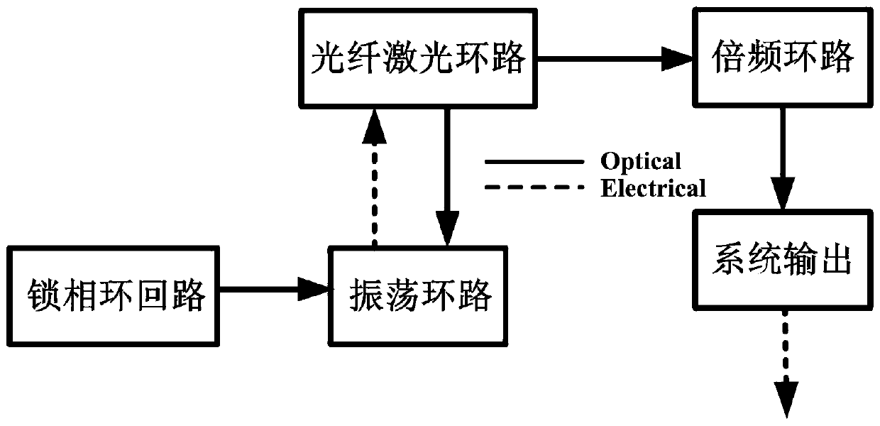
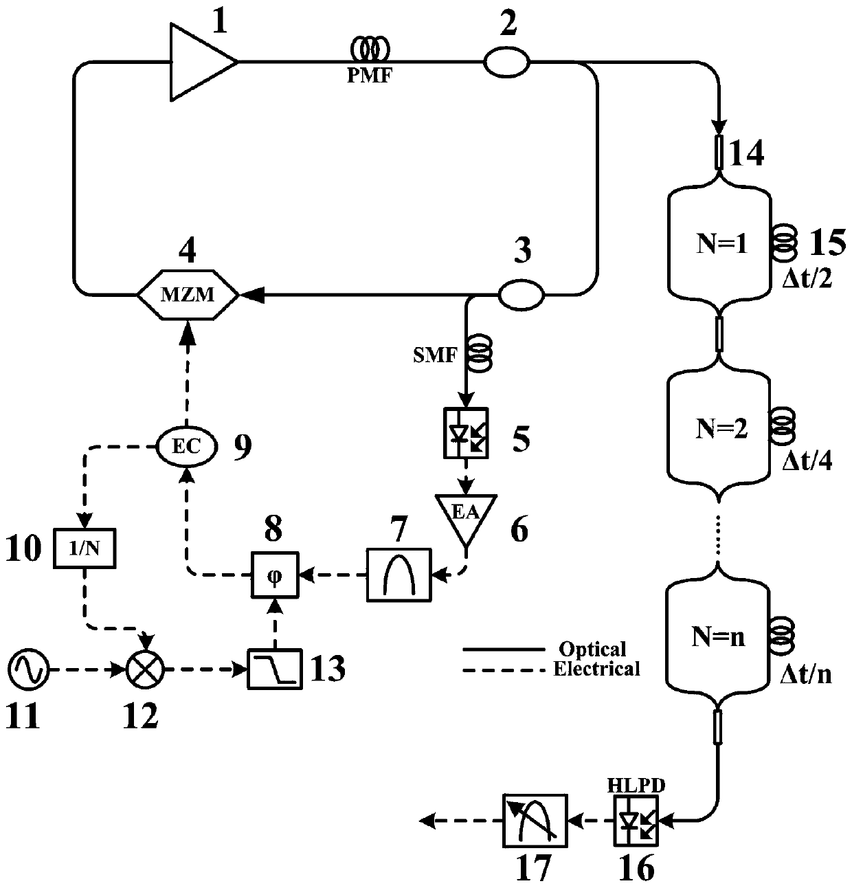
[0031] Such as figure 1 As shown, the present invention is based on the generation device of the coupled photoelectric oscillation optical frequency comb arbitrary frequency multiplication signal, and the whole system includes a fiber laser loop, an oscillation loop, a phase-locked loop loop, and a frequency multiplication loop. Such as figure 2 As shown, the fiber laser loop is composed of optical amplifier 1, 1×2 optical coupler 2, 1×2 optical coupler 3, and electro-optic modulator 4; the oscillation loop is composed of photodetector 5, electrical amplifier 6, and bandpass filter 7. The electric phase shifter 8 and the electric power divider 9 are composed; the phase-locked loop circuit is composed of the frequency divider 10, the reference source 11,...


PUM


Abstract

The invention discloses a device for generating arbitrary frequency multiplication signals of optical frequency combs on basis of a coupled type optoelectronic oscillator. According to the device, a phase locked loop is utilized to lock the phase of the oscillation signals of the coupled optoelectronic oscillator to a highly-stable reference source, so that low-phase-noise and high-stability radiofrequency signals can be generated; the synchronous matching of lock frequencies and optical fiber laser modes is realized, and therefore, stable optical frequency comb output is realized; and sincethe optical frequency combs undergo the loops of optical fiber delay lines of different lengths, an optical coupler couples the optical frequency combs undergoing different time delay, and then optical frequency combs of any multiplied frequencies can be generated. The device of the present invention can be suitable for providing stable optical signal sources for systems such as planetary detection, fiber optic communication, and attosecond pulse systems.

Description

technical field [0001] The invention belongs to the field of optoelectronic technology, in particular to a device for generating arbitrary frequency multiplied signals based on a coupled optoelectronic oscillation optical frequency comb. Background technique [0002] The steady development of modern science and technology is inseparable from the advancement of precision metrology science. The emergence of optical frequency combs has realized the precise connection between microwave frequencies and optical frequencies. Optical frequency comb is a special laser light source, its spectrum is composed of a series of evenly spaced and comb-shaped frequency components with coherent and stable phase relationship. Scientists take advantage of its broad spectrum, high stability, and low phase noise characteristics to have a wide range of applications in exoplanet detection, optical fiber communication, attosecond pulse generation, verification of basic physical laws, arbitrary wavefo...

Claims


Application Information

Patent Timeline
Patent Type & Authority Applications(China)
IPC IPC(8): G02F2/02G02B6/42
Inventor 金晓峰邱纪琛金向东余显斌丛波谭庆贵
Owner ZHEJIANG UNIV
Learn More