Environment-friendly dirt removing system

An environmental protection and dredging device technology, which is applied in the direction of earth mover/shovel, mechanically driven excavator/dredger, construction, etc., can solve the problems of increasing silt water content, long processing cycle, waste of water resources, etc. , to achieve the effect of reducing space requirements, saving manufacturing costs, and convenient operation

Active Publication Date: 2019-06-28
天津市雷升科技有限公司
View PDF6 Cites 10 Cited by
  • Summary
  • Abstract
  • Description
  • Claims
  • Application Information

AI Technical Summary

Problems solved by technology

This device has the following defects: (1) the filtering efficiency of the screen is limited. If the filtering effect of the screen is to be guaranteed, the amount of sludge transported by the lifting device needs to be limited, thereby restricting the dredging efficiency; To a certain extent, it can accelerate the separation of impurities and silt, but the water content of silt is increased after washing the silt with water, which not only wastes water resources, but also increases the burden of subsequent transportation of silt; (3) the whole device provides walking power through the walking device , due to the complex working environment at the bottom, there may be undulating terrain, which will not bring certain resistance to the advancement of the device, resulting in the inability of the cleaning device to effectively sweep the silt into the lifting devi

Method used


Image

  • Environment-friendly dirt removing system
  • Environment-friendly dirt removing system
  • Environment-friendly dirt removing system

Examples


Embodiment 1

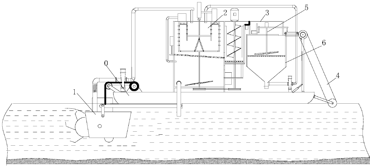
[0042] refer to figure 1 , a garbage disposal device proposed by the present invention, comprising a hull 0, a dredging unit 1, a silt separation unit 2 and a silt collection box 3 which are sequentially arranged on the hull 0 according to the process flow sequence; the dredging unit 1 is used for grabbing The sludge is taken and fed into the sludge separation unit 2; the sludge separation unit 2 is used for filtering and dehydrating the sludge; the silt collecting tank 3 is used for collecting the filtered and dehydrated sludge.

[0043] refer to Figure 6 , the dredging unit 1 includes a mud loosening mechanism connected to the bottom of the hull O, and a silt pump 223 that feeds silt from the mud loosening mechanism into the sludge separation unit.

[0044] refer to Figure 5 , the mud loosening mechanism includes a feed box 11 with a mud flow passage, a rotating shaft connected in the mud flow passage, and a plurality of shifting plates 13 distributed along the axial dir...

Embodiment 2

[0072] The difference between this embodiment and Embodiment 1 is that this embodiment also discloses the following features:

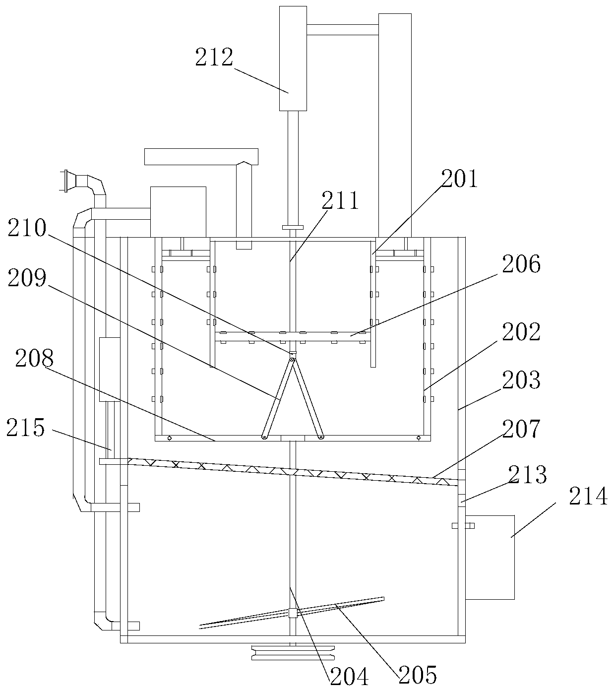
[0073] refer to Figure 7 , the guide screen 207 is movably connected to the outer box 203, and one side of the guide screen 207 is drivingly connected to the piston end of the blanking cylinder 215; the outer box 203 is also provided with The impurity outlet 213, the impurity outlet 213 is located directly below the sewage discharge hole, the guide screen 207 can be driven by the feeding cylinder 215 to the impurity outlet 213, the side of the impurity outlet 213 An impurity collection box 214 is provided.

[0074] It is mentioned in Embodiment 1 that when the impurities in the first inner box 201 need to be taken out, the cylinder 212 needs to be used to control the material baffle plate 206 to move upward. However, due to the deep depth of the first inner box 201 and the limited length of the suspender 209, it is found in actual operation that th...

Embodiment 3

[0079] The difference between this embodiment and the foregoing embodiments is that this embodiment also discloses the following features:

[0080] refer to Figure 10 , the dredging device is installed on the bow of the hull, the water weed removal device is installed on the stern of the hull, the water tank removal device includes a salvage unit 4, a cutting unit, a crushing unit and a grass box 6; the grass box 6 There are two material outlets, both of which are closed by control valves, and one of the material outlets extends into the first inner box 201 through a forage pipe, and a material pump 56 is installed on the forage pipe.

[0081] The salvage unit 4 is used to salvage aquatic plants on the river surface and send them into the grass collecting box 6 . In this process, the aquatic plants are cut by the cutting unit to reduce the size of the strip-shaped aquatic plants, and then the aquatic plants are crushed by the crushing unit to further reduce the size of the a...


PUM


Abstract

The invention relates to an environment-friendly dirt removing system. A dirt removing device comprises a dirt removing unit, a dirt separation unit and a dirt collecting box, wherein the dirt separation unit comprises an outer box body, a first inner box body and a second inner box body; a waterweed removing device comprises a pulling unit, a cutting unit, a crushing unit and a waterweed collecting box; two discharge ports of the waterweed collecting box are both closed by control valves; one discharge port extends into the first inner box body through a waterweed pipe; and a waterweed material pump is arranged on the waterweed pipe. According to the system, the functions of dirt removing and waterweed removing are integrated, and the two operations can be carried out simultaneously, thus, the system is suitable for river channel treatment operations in various environments with high working efficiency. The waterweed removing device can fully utilize the dirt separation unit of the dirt removing system device, so that the dirt separation unit can not only separate the dirt but also dehydrate the waterweed. Due to the fact that a device for dehydrating the waterweed is not needed to be additionally designed as well as no space of a ship body needs to be occupied, the technical effects of saving the manufacturing cost of the device and reducing the space requirement for the shipbody are achieved.

Description

technical field [0001] The invention relates to the field of desilting, in particular to an environment-friendly decontamination system. Background technique [0002] There are many rivers and lakes in our country, and the problem of sedimentation is very serious. The sedimentation causes the river bed to rise, which not only affects flood control and threatens the safety of people's lives and property, but also makes it difficult for various functions such as drainage, irrigation, water supply, and navigation to be properly performed. Seriously restricting the comprehensive utilization of water resources and exacerbating the deterioration of the water environment, it is necessary to regularly dredge the drainage to ensure the smooth flow of the river. [0003] The invention patent with the patent number of 201811268780.2 discloses a river dredging device for water conservancy projects. The device extracts the sludge from the bottom of the water and sends it into the classif...

Claims


Application Information

Patent Timeline
IPC IPC(8): E02F5/28E02F3/88E02F3/90E02F3/92E02F7/04E02F7/06
Inventor 邱宪涛裴兰英李兴池孙秀娟
Owner 天津市雷升科技有限公司
Why Eureka
Try Eureka