A Low Loss Wide Beam Circularly Polarized Waveguide Cross Slot Antenna

A technology of circularly polarized waves and cross slots, which is applied in the field of antennas, can solve problems such as difficulty in realizing circularly polarized work, large size of waveguide horn antennas, and difficulty in wide-angle electrical scanning, etc., to achieve low cost, overcome large loss, and low loss Effect

Active Publication Date: 2021-03-26
BEIJING RES INST OF TELEMETRY +1
View PDF9 Cites 0 Cited by
  • Summary
  • Abstract
  • Description
  • Claims
  • Application Information

AI Technical Summary

Problems solved by technology

[0003] In the millimeter-wave terahertz frequency band, common microstrip and dielectric circularly polarized antennas are used for phased array electronic scanning, which have the disadvantages of large dielectric loss and poor adaptability in harsh environments.
The common waveguide horn antenna is difficult to be used for wide-angle electronic scanning due to its large size, and the short-cut waveguide is difficult to achieve circular polarization.

Method used


Image

  • A Low Loss Wide Beam Circularly Polarized Waveguide Cross Slot Antenna
  • A Low Loss Wide Beam Circularly Polarized Waveguide Cross Slot Antenna
  • A Low Loss Wide Beam Circularly Polarized Waveguide Cross Slot Antenna

Examples


Embodiment Construction

[0029]The present invention will be further described below with reference to the accompanying drawings.

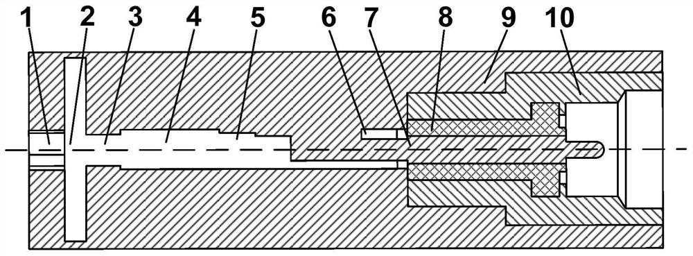
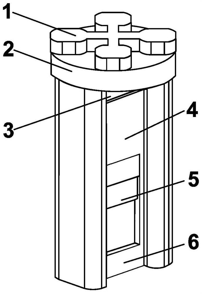
[0030]figure 1 A cross-sectional view of the present invention, is known from the figure, the antenna is from cross radiation slits 1, the coupling chamber 2, the feed slit 3, the ridge waveguide 4, the ridge waveguide transform section 5, the ridge waveguide 6, the coaxial probe 7, The probe fixation medium 8, the antenna housing 9, the coaxial housing 10.

[0031]Among them, the cross radiation slit 1, the coupling chamber 2, the feed slit 3, the ridge waveguide 4, the ridge waveguide transform section 5, the matching ridge waveguide 6 is laminated from top to bottom, and the bonding antenna housing 9 constitutes an antenna body. Process production and processing of welding can be used in segmented machining. Coaxial probe 7, the probe fixing medium 8 and the coaxial housing 10 are closely bonded to form a common SMP interface.

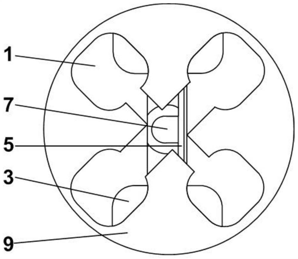
[0032]Such asfigure 1 withfigure 2 As shown, the bottom...


PUM

PropertyMeasurementUnit
thicknessaaaaaaaaaa
thicknessaaaaaaaaaa
diameteraaaaaaaaaa

Abstract

The invention relates to a low-loss wide-beam circularly-polarized waveguide cross slot antenna, and the antenna is composed of a cross radiation slot, a coupling cavity, a feed slot, a ridge waveguide, a ridge waveguide conversion section, a matching ridge waveguide, a coaxial probe, a probe fixing medium, an antenna housing and a coaxial housing. The cross radiation slot, the coupling cavity, the feed slot, the ridge waveguide, the ridge waveguide conversion section, the matching ridge waveguide and the antenna housing form an antenna main body. The coaxial probe, the probe fixing medium andthe coaxial housing form an SMP interface to form a feed coaxial line of the antenna. By adopting the mode that the ridge waveguide feeds the cross radiation slot through the coupling cavity, the size and loss of the antenna are reduced while circular polarization is realized, and the beam width of the antenna is increased. The antenna can be used as a single antenna and can also be used as a wide-angle scanning phased-array antenna array element.

Description

Technical field[0001]The invention belongs to the field of antenna, and in particular, the present invention relates to a low loss, width beam, and a circularly polarized waveguide cross gap antenna.Background technique[0002]Wide-beam circularized antennas are widely used in communication and radar. To achieve mobile user high-size data transmission and wide high resolution imaging, modern communication, and radar systems use phase-controlled array of electric scanning technology, and development to millimeters or even higher frequency bands.[0003]In a millimeter waveheez band, common microstrip and medium-polarized antennas are used in phased array of electrical scans, and have a shortcomings of poor energy in harsh environments. The common waveguide speaker antenna is difficult to use for a wide-angle electric scan due to large size, and the short waveguide is difficult to achieve circularly.Inventive content[0004]The technical problem solved by the present invention is to overcom...

Claims


Application Information

Patent Timeline
Patent Type & Authority Patents(China)
IPC IPC(8): H01Q13/10H01Q1/36H01Q1/50
Inventor 谷胜明刘昊
Owner BEIJING RES INST OF TELEMETRY
Why Eureka
Try Eureka