Salvage device and construction method of drill bit of spin dig drill

A salvage device and rotary drilling technology, which is applied to earth-moving drilling, cleaning equipment, wellbore/well components, etc., can solve the problems of difficult operation of the grab bucket structure, collapsed holes, easy falling off, etc., so as to reduce manual entry. The probability of operation to the wellbore, improve the success rate, and avoid the effect of sticking

Active Publication Date: 2019-07-05
CCCC SECOND HARBOR ENG +1
View PDF8 Cites 14 Cited by
  • Summary
  • Abstract
  • Description
  • Claims
  • Application Information

AI Technical Summary

Problems solved by technology

In the salvage of drill pipes, manual salvage is mainly used. Usually the underwater environment is relatively harsh, the depth of the water is relatively deep, and the proportion of underwater mud is too large, there is a risk of hole collapse, the underwater vision is blurred, and the underwater working time is long , and the purpose of salvaging the drill pipe is often not achieved by launching once, and multiple launches are required, which poses a great safety risk to the launching staff
If the drill pipe is too thick due to the drilling slag and the drill bit is wrapped by the drill slag, manual labor often cannot achieve the effect of successfully salvaging the drill pipe
[0004] Chinese patent document CN101382049A has recorded a kind of salvage method of the bucket door of a rotary drilling rig, and salvages by adopting a scheme similar to a steel wire cage; but for the rotary drilling bit, the structure of the steel wire cage is difficult to be placed on the rotary drilling bit
Chinese patent document CN101382049A describes a drilling tool fishing device, which uses a structure similar to a hydraulic grab to grab the drilling tool, but the gap between the rotary drilling bit and the inner wall of the well hole (9) is small, and the grab structure It is difficult to operate, and the downhole hydraulic supply in the wellbore (9) is also difficult, and an additional hydraulic system is required
Chinese patent document CN204492730U describes a rotary drilling rig and its drilling bucket fishing device, which uses a barb structure to hook the rotary drilling bit, but the positioning of this solution is relatively difficult, and it can only be aimed at specific types of drilling buckets. And it is easy to fall off during lifting

Method used


Image

  • Salvage device and construction method of drill bit of spin dig drill
  • Salvage device and construction method of drill bit of spin dig drill
  • Salvage device and construction method of drill bit of spin dig drill

Examples


Embodiment 1

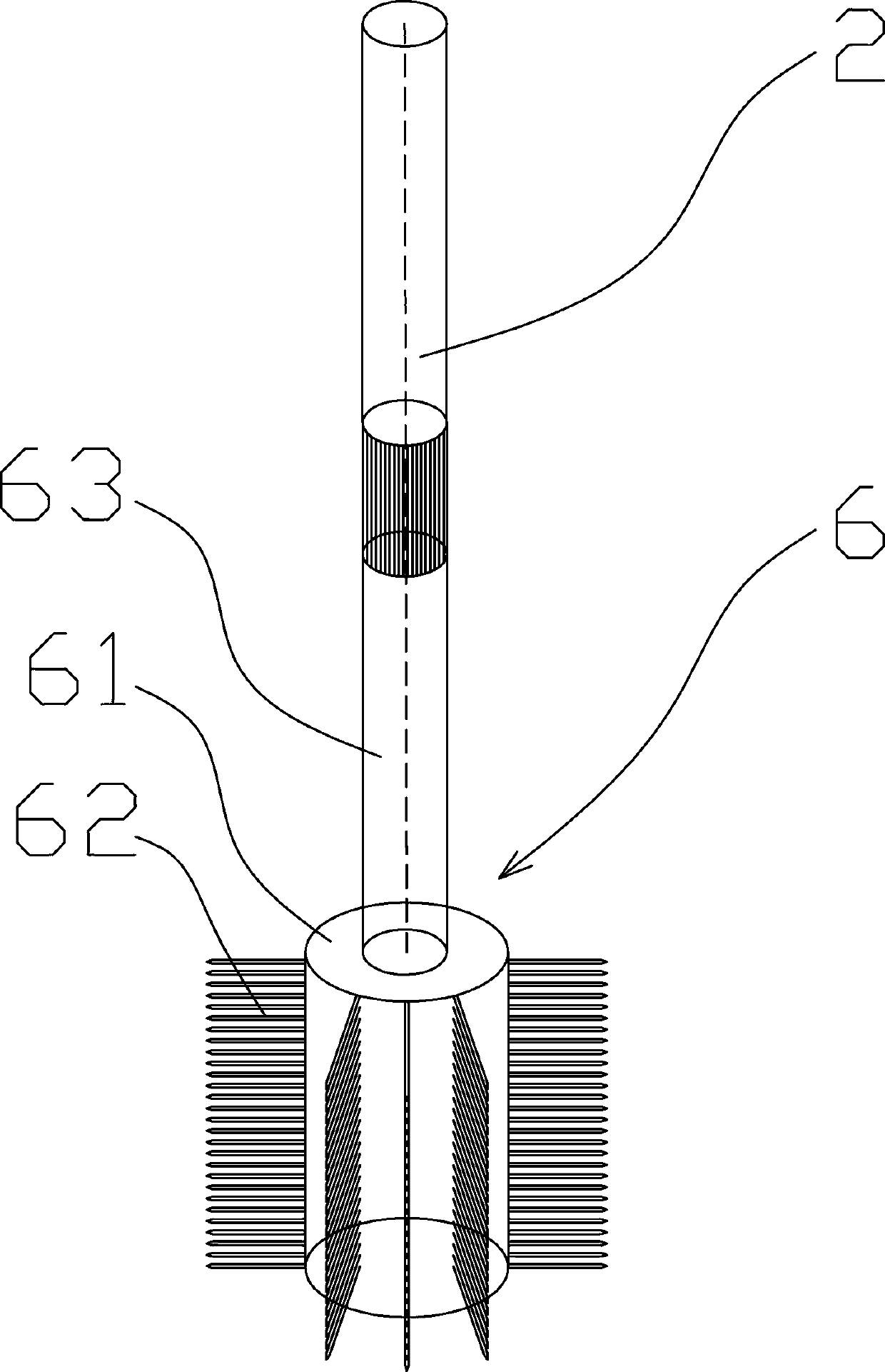
[0045] Such as image 3 Among them, a rotary drilling drill bit fishing device, which includes a comb-shaped rotary head 6;

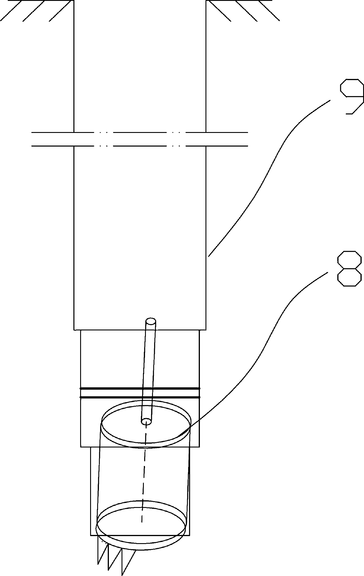
[0046] In the comb-shaped rotor 6, the lower end of the first high-pressure water pipe 63 is connected to the rotor cylinder 61, and the inner or outer wall of the rotor cylinder 61 is provided with radially distributed rotor nails 62 or elastic steel wires. The top of the high-pressure water pipe 63 is connected to the drill pipe 2, and the side wall or / and bottom of the rotary head cylinder 61 are provided with water outlet holes. With this structure, the comb-shaped rotary head 6 is used to clean the drilling slag in the well hole 9 and the drilling slag and clay on the surface of the rotary drilling bit 8 , and to open up a reliable channel for the fishing of the rotary drilling bit 8 . And can correct collapse hole and shrinkage cavity defects. The set rotating head nails 62 or elastic steel wires break up the drilling slag, and transport it to t...

Embodiment 2

[0059] A construction method using the above-mentioned rotary drilling drill bit fishing device, comprising the following steps:

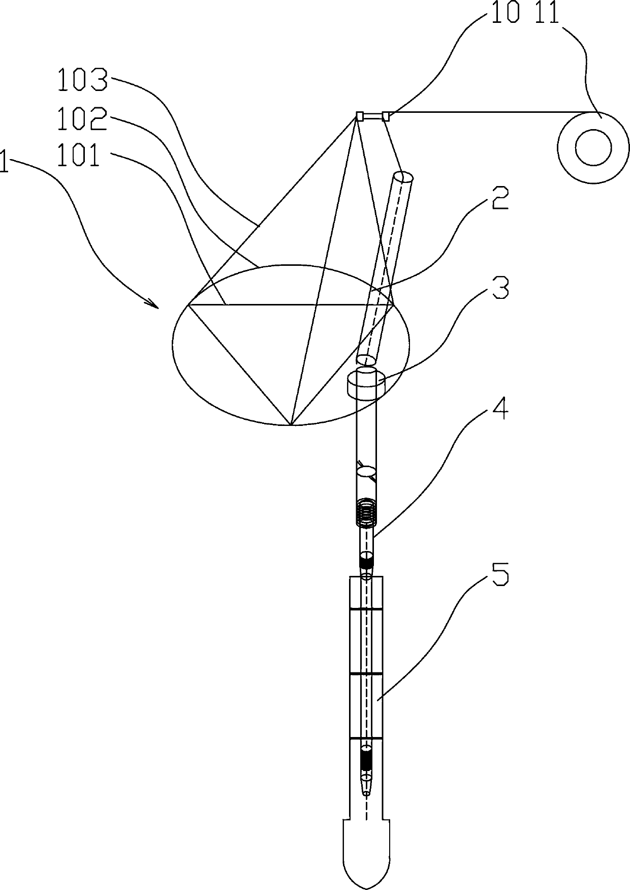
[0060] S1. Install the complete structure of the drilling rig including the drill rod support 1, hoisting device 11 and disc drill 3. The drill rod 2 is slidably installed in the guide wheel 10. The drill rod 2 is a hollow drill rod with a standard section of 5m and a diameter of 12cm. The lower end of the drill pipe 2 is fixedly connected with the comb-shaped rotary head 6 through threads, and the top end of the drill pipe 2 is connected with the mud pump. A high-pressure water pipe 63 circulates for flushing, and the disc drilling rig 3 drives the drill pipe to rotate as a whole to remove the drilling slag and viscous mud in the well hole 9 above the rotary drilling bit 8 and on the surface of the rotary drilling bit 8, so as to facilitate subsequent lifting and rotary drilling The construction of the drill bit 8, decompression drilling and lifti...


PUM


Abstract

The invention discloses a salvage device and a construction method of a drill bit of a spin dig drill. The salvage device comprises a comb-shaped rotating drill bit, a flat bamboo cutting type drill,and an anchor type drill bit; and in the comb-shaped rotating drill bit, the lower end of a first high pressure water pipe is connected with a rotating drill bit barrel body, radially distributed rotating drill bit irons nail or elastic steel wire are arranged on the inner wall or the outer wall of the rotating drill bit barrel body, the top end of the first high-pressure water pipe is connected with a drill pipe, and water outlet holes are formed in the side wall or / and bottom of the rotating drill bit barrel body. During construction, the comb-shaped rotating drill bit removes drilling slagon the drill bit of the spin dig drill, and the drill bit of the flat bamboo cutting type drill removes attachment in the drill bit of the spin dig drill; and the anchor type drill bit lifts the drillbit of the spin dig drill. According to the fishing device and the construction method of the drill bit of the spin dig drill, the drilling slag in a borehole is cleaned in the early stage by the comb-shaped rotating drill bit and the drill of the flat bamboo cutting type drill, a passage in the borehole is unobstructed, and the success rate of drill bit salvage of the spin dig drill bit is greatly increased; and the anchor type drill bit adopts an internal bracing structure, the problem of small gap between the drill bit of the spin dig drill and the inner wall of the borehole is solved, andthe success rate of salvage is significantly increased.

Description

technical field [0001] The invention relates to the field of bridge construction, in particular to a rotary drilling drill bit fishing device and a construction method. Background technique [0002] Bored pile foundations are widely used in today's bridge construction process, especially under the conditions of some cross-river and urban soft ground geological environment factors, the pile foundation design is generally the bridge construction mode of bored pile foundation columns, because The pile foundation is the foundation part of the bridge construction, and the pile foundation must be driven into the bearing layer to provide a stable bearing capacity. [0003] The bearing layer of the pile foundation is a hard rock layer with a deep buried depth and stable geological conditions. When the bored pile is used for construction, due to the excessive consumption of the drill pipe, the brittle fracture of the drill pipe causes the accident that the drill bit breaks and falls...

Claims


Application Information

Patent Timeline
Patent Type & Authority Applications(China)
IPC IPC(8): E21B31/00E21B31/20E21B37/00
CPCE21B31/00E21B31/20E21B37/00
Inventor 赵靖周益军樊甘露王加斌夏创汪洋廖兴峰赵映斌张志刚
Owner CCCC SECOND HARBOR ENG
Why Eureka
Try Eureka