Double-support flange machining machine

A processing machine and double support technology, applied in the field of double support flange processing machines, can solve the problems of high difficulty of flange butt joint, flange corrosion, scratches, bumps, flange failure, etc., to reduce the difficulty of repair and Repair cost, improve repair efficiency, and ensure the effect of smooth rotation

Pending Publication Date: 2019-07-09
吉林市维特新工贸有限公司
View PDF0 Cites 4 Cited by
  • Summary
  • Abstract
  • Description
  • Claims
  • Application Information

AI Technical Summary

Problems solved by technology

[0002] Flange is a commonly used connection and sealing structure on various containers, pipelines and other equipment. The butt joint surfaces of existing flanges are usually flat or grooved occlusal surfaces, which meet the sealing requirements, and the precision requirements of the flange butt joint surfaces are relatively high. , but in daily production and use, the situation that the flange is corroded, scratched, and bumped cannot be completely avoided, so it will cause defects such as damage and cracks on the flange butt joint surface. The butt joint surface is repaired. When repairing, the metal material is first filled into the damaged part of the flange butt joint surface by metal welding process, and then the repaired part is manually polished to a flat surface, that is, the rep

Method used


Image

  • Double-support flange machining machine
  • Double-support flange machining machine
  • Double-support flange machining machine

Examples


Example Embodiment

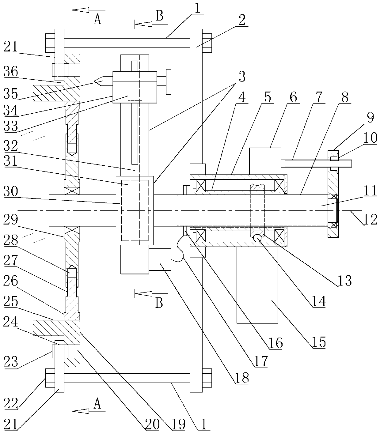
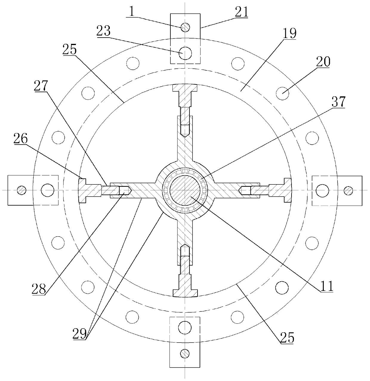
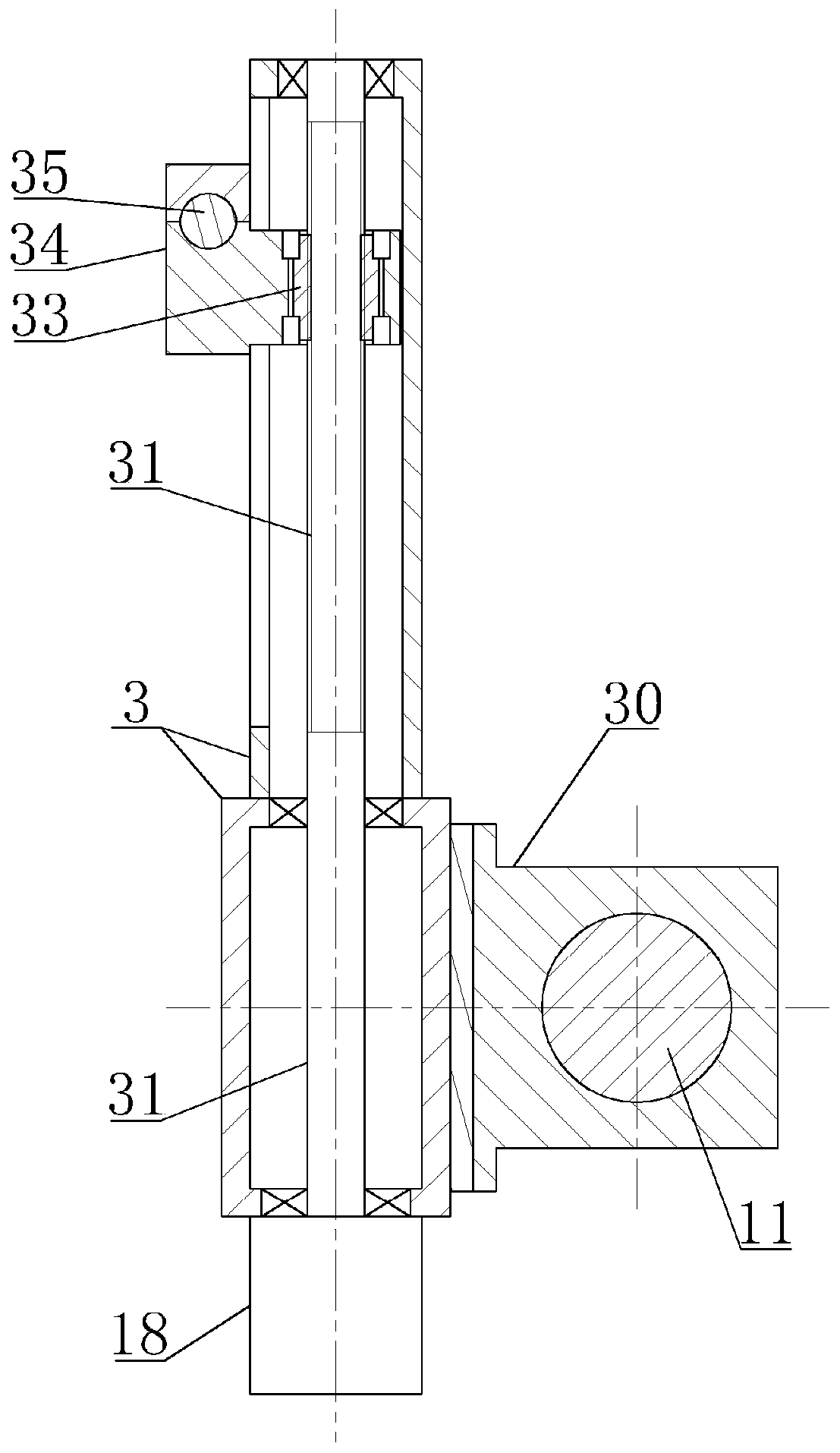
[0015] The double-support flange processing machine has a main shaft 11 on which an inner support plate 29, a tool holder 30, and a shaft sleeve 4 are sequentially sleeved; the inner support plate is rotatably connected with the main shaft, and the outer edge of the inner support plate is circumferentially A plurality of screw holes 28 are evenly distributed, and each screw hole is equipped with a screw 27. One end of each screw is screwed with the corresponding screw hole, and the other end of each screw is provided with a foot 26; the tool holder is fixedly connected with the main shaft, The arm 3 is fixedly mounted on the frame, and the feed screw 31 and the feed motor 18 are mounted on the arm. The feed motor is fixed on the arm, and the motor shaft of the feed motor is dynamically connected with the screw. Rotatingly connected with the swing arm, the axis line 32 of the feed screw is perpendicular to the axis line 12 of the spindle. The feed screw is equipped with a feed sc...


PUM


Abstract

The invention discloses a double-support flange machining machine. The machine is used for machining a flange on equipment on site, and the main shaft of the double-support flange machining machine issequentially provided with an inner supporting plate, a knife rest and a shaft sleeve, plurality of screw holes are formed in the outer edge surface of the inner supporting plate, screw rods are arranged in the screw holes, supporting legs are arranged at the outer ends of the screw rods, a rotating arm is arranged on the knife rest, a feeding screw and a feeding motor are arranged on the rotating arm, a feeding screw is arranged on the feeding screw, a sliding knife holder is arranged on the feeding nut, an organic frame is arranged on the shaft sleeve, an outer supporting plate is fixedly arranged on the machine frame, the rotating motor, a plurality of pull rods are uniformly distributed on the periphery of the outer support plate, a pull rod nut is arranged at the outer end of each pull rod, the rotary motor drives the shaft sleeve to rotate, the longitudinal pushing motor is provided with a longitudinal pushing screw, a longitudinal pushing nut on the longitudinal pushing screw is provided with a connecting plate, the connecting plate is fixedly connected with the main shaft, the inner supporting plate is arranged in the flange hole, the pull rod is connected with the flangebolt hole, and therefore the rack is fixed on the flange plate, high-precision machining and repairing can be carried out on the butt joint surface of the flange on site, the repairing difficulty andthe repairing cost are reduced, the repairing efficiency is improved, and the working time is saved.

Description

technical field [0001] The invention relates to a special machine for flange processing, in particular to a double-support flange processing machine. Background technique [0002] Flange is a commonly used connection and sealing structure on various containers, pipelines and other equipment. The butt joint surfaces of existing flanges are usually flat or grooved occlusal surfaces, which meet the sealing requirements, and the precision requirements of the flange butt joint surfaces are relatively high. , but in daily production and use, the situation that the flange is corroded, scratched, and bumped cannot be completely avoided, so it will cause defects such as damage and cracks on the flange butt joint surface. The butt joint surface is repaired. When repairing, the metal material is first filled into the damaged part of the flange butt joint surface by metal welding process, and then the repaired part is manually polished to a flat surface, that is, the repair is completed...

Claims


Application Information

Patent Timeline
IPC IPC(8): B23D79/00
CPCB23D79/00
Inventor 焦维光刘福贵
Owner 吉林市维特新工贸有限公司
Why Eureka
Try Eureka