Vertical cooling machine with moving plate type discharging device and cooling method
A technology of moving plates and coolers, which is applied in the fields of vertical coolers and cooling, sinter coolers and sinter cooling. Low-level problems, to achieve the effect of flexible layout, less equipment maintenance, and high hot air temperature
- Summary
- Abstract
- Description
- Claims
- Application Information
AI Technical Summary
Problems solved by technology
Method used
Image

Examples
Embodiment 1
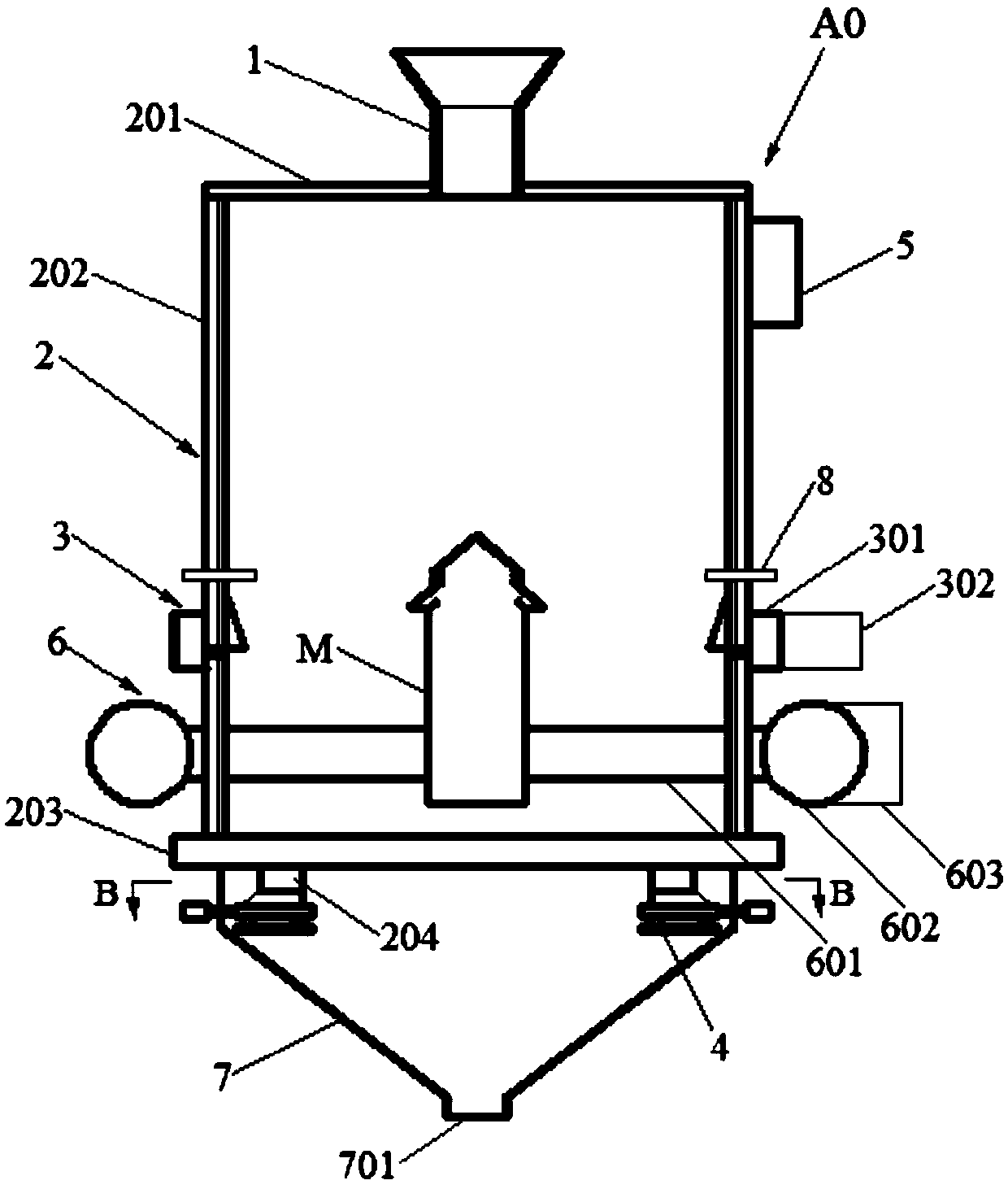
[0083] Such as figure 1 As shown, a vertical cooler with a movable plate discharge device, the vertical cooler A0 includes a material distribution device 1 , a tower body 2 , an edge air supply device 3 and a movable plate discharge device 4 . The tower body 2 includes a tower top 201 , a tower wall 202 and a tower bottom 203 . The tower top 201 is arranged on top of the tower wall 202 . The column bottom 203 is provided at the bottom of the column wall 202 . The distribution device 1 is arranged above the tower top 201 and communicates with the inside of the tower body 2 . The side air supply device 3 is arranged at the middle and lower part of the tower wall 202 . The bottom 203 of the tower is provided with a discharge port 204 . The movable plate discharge device 4 is arranged below the discharge opening 204 . A hot air outlet 5 is provided on the top of the tower wall 202 .
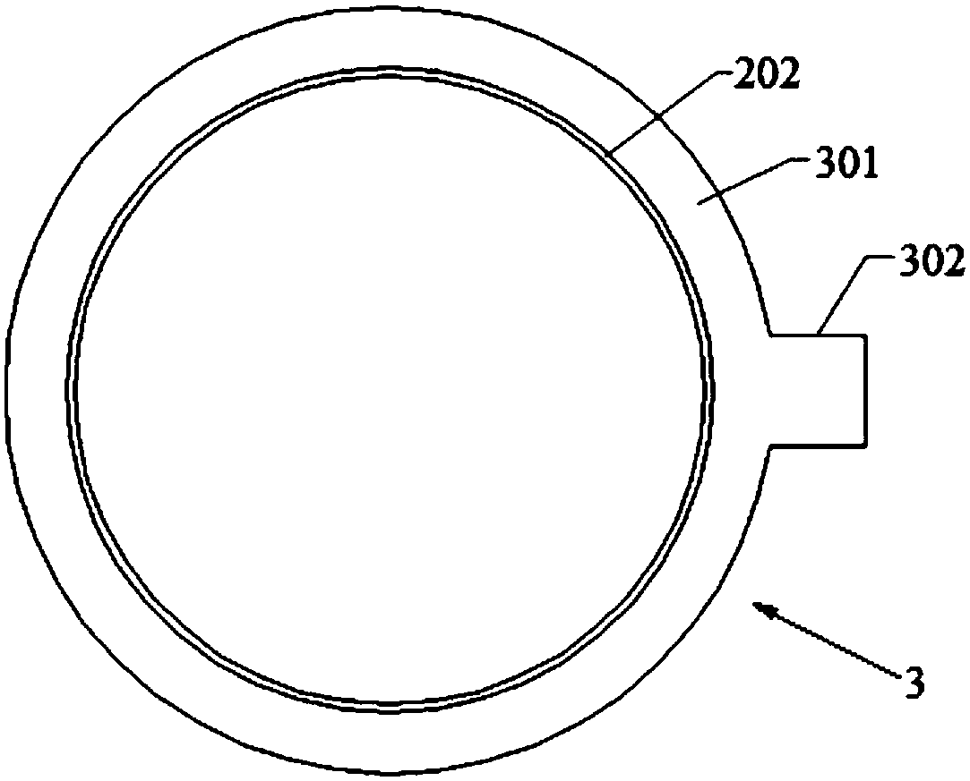
[0084] Such as image 3 As shown, the edge air supply device 3 includes an edge air supply...
Embodiment 2
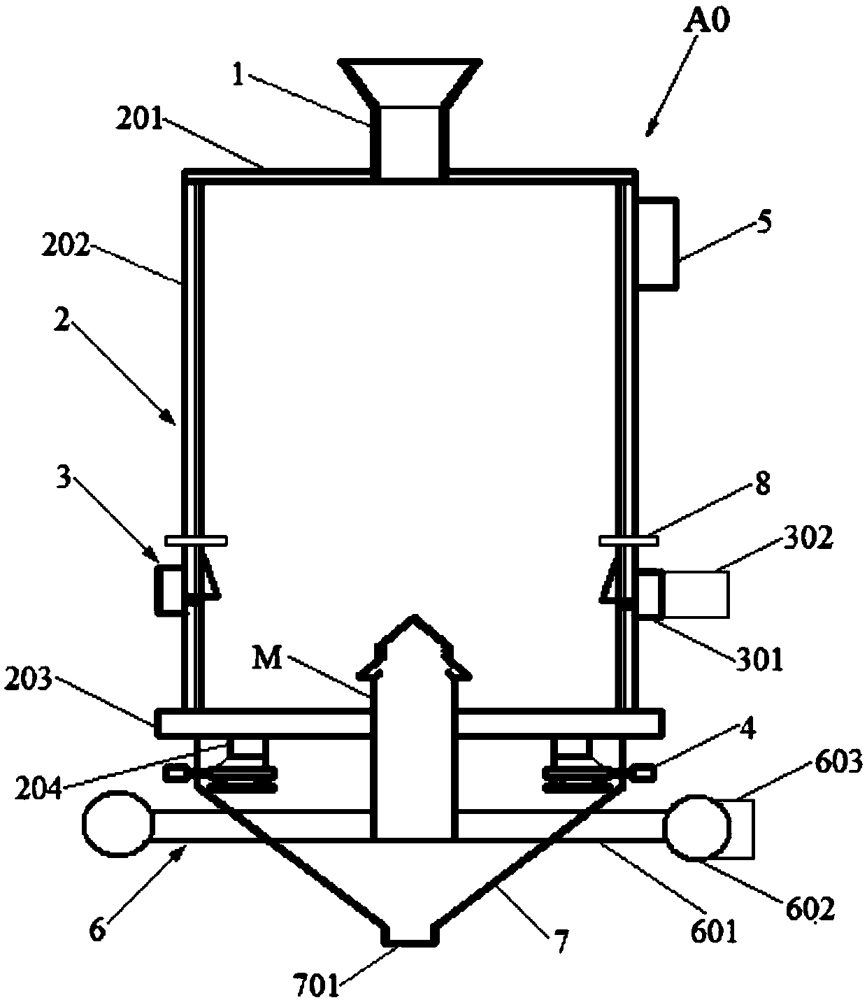
[0091] Such as figure 2 As shown, embodiment 1 is repeated, except that the wind cap M of the central air supply device 6 is located at the center of the bottom of the tower body 2 and extends upward into the inner space of the tower body 2 . The central air supply duct 602 is located outside the discharge chute 7 . One end of each central air supply branch pipe 601 communicates with the central air supply duct 602 and the other end communicates with the lower part of the air cap M through the discharge chute 7 .
Embodiment 3
[0093] Embodiment 1 is repeated, except that the vertical cooler A0 is provided with a plurality of temperature measuring elements 8 on the tower wall 202 along the circumferential direction. The temperature measuring element 8 is located on the upper part of the edge air supply device 3 and extends into the interior of the tower body 2 . The temperature measuring element 8 is a thermocouple temperature sensor.
PUM
 Abstract
Description
Claims
Application Information
 - Generate Ideas
- Intellectual Property
- Life Sciences
- Materials
- Tech Scout
- Unparalleled Data Quality
- Higher Quality Content
- 60% Fewer Hallucinations
Browse by: Latest US Patents, China's latest patents, Technical Efficacy Thesaurus, Application Domain, Technology Topic, Popular Technical Reports.
© 2025 PatSnap. All rights reserved.Legal|Privacy policy|Modern Slavery Act Transparency Statement|Sitemap|About US| Contact US: help@patsnap.com