Machine oil separation and lubrication control system for two-stroke pulse pump

A technology that separates lubrication and control systems. It is applied in the direction of engine control, engine lubrication, and timing lubrication. It can solve problems such as lubricating oil waste, achieve reasonable distribution, reduce exhaust emissions, and reduce consumption.

Inactive Publication Date: 2019-07-09
ZHEJIANG PIONEER MACHINERY & ELECTRON
View PDF4 Cites 0 Cited by
  • Summary
  • Abstract
  • Description
  • Claims
  • Application Information

AI Technical Summary

Problems solved by technology

This technology was applied for an invention patent on June 18, 2009, and the patent application number is: 2009103033665). Because the second cycle of the new two-stroke engine is idling, the engine has no load, so its demand for lubricating oil is only satisfied at the minimum requirements, while the traditional oil pump will make the waste of lubricating oil obvious

Method used


Image

  • Machine oil separation and lubrication control system for two-stroke pulse pump
  • Machine oil separation and lubrication control system for two-stroke pulse pump

Examples


Embodiment Construction

[0013] The following will clearly and completely describe the technical solutions in the embodiments of the present invention with reference to the drawings in the embodiments of the present invention.

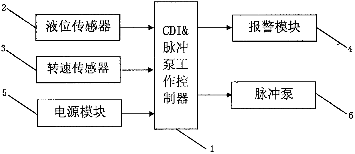
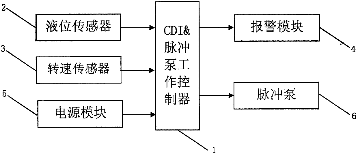
[0014] see figure 1 The present invention provides a technical solution: a two-stroke pulse pump oil separation and lubrication control system, including CDI & pulse pump work controller 1, liquid level sensor 2, speed sensor 3, alarm module 4, power supply module 5 and pulse pump 6; Wherein: the liquid level sensor 2 is connected with the CDI&pulse pump working controller 1, and the alarm module 4 is connected with the CDI&pulse pump working controller 1, wherein the liquid level sensor 2 is used to detect the liquid level of lubricating oil in the oil tank And feed back the oil level height information to the CDI&pulse pump controller 1, and at the same time, when the liquid level is lower than the set threshold, the CDI&pulse pump controller 1 drives the alarm module 4 to p...


PUM


Abstract

The invention provides a machine oil separation and lubrication control system for a two-stroke pulse pump. The machine oil separation and lubrication control system comprises a CDI and pulse pump working controller, a liquid level sensor, a rotation speed sensor, an alarm module, a power supply module and a pulse pump, wherein, the liquid level sensor is connected with the CDI and pulse pump working controller, the alarm module is connected with the CDI and pulse pump working controller, the rotation speed sensor is connected with the CDI and pulse pump working controller, the power supply module is connected with the CDI and pulse pump working controller, and the pulse pump is connected with the CDI and pulse pump working controller. According to the pulse pump machine oil separation andlubrication operation principle in the machine oil separation and lubrication control system, the machine oil separation and lubrication control system of the two-stroke pulse pump is installed in anengine, after the engine is started, the CDI and pulse pump working controller collects information such as the rotation speed, liquid level, and power supply voltage of the engine, and after data are processed, pulse control signals are sent to control the operation of the pulse pump.

Description

technical field [0001] The invention relates to a lubrication control system of a two-stroke engine, in particular to a two-stroke pulse pump engine oil separation lubrication control system. Background technique [0002] As we all know, from the working principle of the two-stroke engine, we know that when the two-stroke engine is working, it will inevitably produce lubricating smoke, which will pollute the environment, especially with the newly designed two-stroke EFI control system (one circle works one circle) idling) to match (the working principle of the new two-stroke engine: the magneto rotates the trigger to generate a signal, the signal of the trigger is rectified by VD1 and then sent to the ECU controller, and the ECU controller sends the fuel injection command to the fuel injector and the spark plug after processing. The ignition time control is issued, and the engine works; the magneto rotates for the second time, and the signal generated by the trigger is input...

Claims


Application Information

Patent Timeline
IPC IPC(8): F01M1/02F01M1/14F01M1/18F01M11/00F02D41/14F02D45/00
CPCF01M1/02F01M1/14F01M1/18F01M11/00F02D41/1401F02D45/00
Inventor 杨慧明何志强
Owner ZHEJIANG PIONEER MACHINERY & ELECTRON
Why Eureka
Try Eureka