Method for controlling metering system having plurality of metering valves

A technology of metering system and metering valve, which is applied in the direction of electric control of exhaust gas treatment device, exhaust gas treatment, mechanical equipment, etc., can solve problems such as the rise of liquid level controller

Active Publication Date: 2019-07-19
ROBERT BOSCH GMBH
View PDF18 Cites 0 Cited by
  • Summary
  • Abstract
  • Description
  • Claims
  • Application Information

AI Technical Summary

Problems solved by technology

This usually results in a surge in level controllers for metering strategies, as the last valve experiences a stronger restriction

Method used


Image

  • Method for controlling metering system having plurality of metering valves
  • Method for controlling metering system having plurality of metering valves
  • Method for controlling metering system having plurality of metering valves

Examples


Embodiment Construction

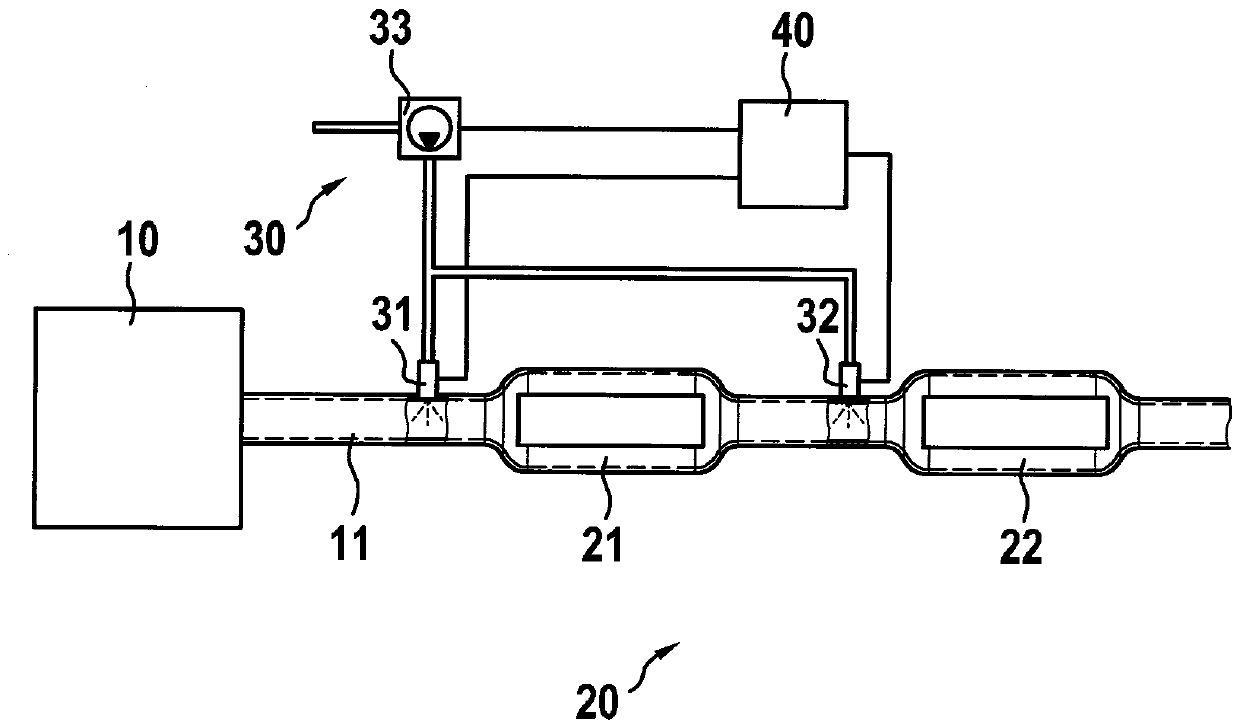
[0016] The internal combustion engine 10 has in its exhaust system 11 an SCR catalytic converter system 20 which is located in the figure 1 is shown in . It has two SCR catalytic converters 21 , 22 , wherein the catalytic converter material of the first SCR catalytic converter 21 is arranged on a particle filter (SCR on filter; SCRF). A metering system 30 is provided for metering the aqueous urea solution into the exhaust system 11 . It has a first metering valve 31 upstream of the first SCR catalytic converter 21 and a second metering valve 32 between the two SCR catalytic converters 21 , 22 . The delivery pump 33 delivers the aqueous urea solution from a reducing agent tank (not shown). In this case, the aqueous urea solution is conveyed via a reducing agent line which branches off downstream of a feed pump 33 into two metering valves 31 , 32 . The first metering valve 31 has a structurally relevant first maximum metering quantity dm max,31 , and the second metering valv...


PUM


Abstract

The present invention relates to a method for controlling a metering system having a plurality of metering valves. A first reduction factor is calculated based on the desired metering requirements forthe metering valves and the maximum possible total metering amount of all metering valves.

Description

technical field [0001] The invention relates to a method for controlling a metering system with a plurality of metering valves. Furthermore, the present invention relates to a computer program that executes each step of the method and a machine-readable storage medium that stores the computer program. Finally, the invention relates to an electronic controller which is configured to carry out the method. Background technique [0002] A metering system for an SCR catalytic converter system with one or more metering valves implements the desired quantities requested by the metering strategy as quickly and accurately as possible by using known information The quantity request is converted into an actuation of the metering valve, the information being information about the possible flow rate of the corresponding metering valve or information about the system pressure. However, if the quantity requirement exceeds the physical capacity of the system (i.e. the maximum mass flow th...

Claims


Application Information

Patent Timeline
IPC IPC(8): F01N9/00F01N3/20
CPCF01N9/00F01N3/208F01N3/2066F01N13/0093F01N2610/02F01N2610/146F01N2610/1453F01N2900/1812F01N2900/1822F01N2900/1821Y02T10/12F01N2610/1433
Inventor E.博斯S.伯姆
Owner ROBERT BOSCH GMBH
Why Eureka
Try Eureka