
Large bearing bush integrated with pressure sensor

A pressure sensor and sensor probe technology, which is applied in the measurement of fluid pressure, the measurement of fluid pressure through electromagnetic components, and the measurement of fluid pressure by piezoelectric devices, can solve the problem of destroying the combination of crankshaft and bearing surface, oil film pressure surface damage, engineering Problems such as poor application performance, to achieve the effect of good practicability, sufficient measurement point data, and increased measurement point layout

Pending Publication Date: 2019-07-19
HARBIN ENG UNIV
View PDF0 Cites 0 Cited by
  • Summary
  • Abstract
  • Description
  • Claims
  • Application Information

AI Technical Summary

Problems solved by technology

The structure of the broken bearing pad is to drill several through holes on the entire bearing pad surface according to the position of the pressure measuring point, and then the through holes are connected with the external measurement circuit, and the oil film pressure is measured after the oil film pressure is drawn out, and the oil film pressure is measured by opening the through hole. Lubricating oil leakage, oil film pressure surface damage and orifice runoff enlargement and other serious instability effects
Installing a pressure sensor on the crankshaft can accurately measure the oil film pressure on the moving surface, but opening a sensor installation hole on the crankshaft will greatly reduce the strength of the crankshaft, destroy the bonding condition between the crankshaft and the bearing bush surface, and cause huge defects in the real-time change of the measurement position , and adopt the measurement method of installing the pressure sensor on the surface of the crankshaft, it is necessary to install a slip ring device at the output end of the crankshaft
When multi-point measurement is used, the number of slip ring output channels will be greatly increased, and the engineering application performance is extremely poor, so it cannot be used in actual installation

Method used


Image

  • Large bearing bush integrated with pressure sensor
  • Large bearing bush integrated with pressure sensor
  • Large bearing bush integrated with pressure sensor

Examples


Embodiment Construction

[0017] The present invention is described in more detail below in conjunction with accompanying drawing example:

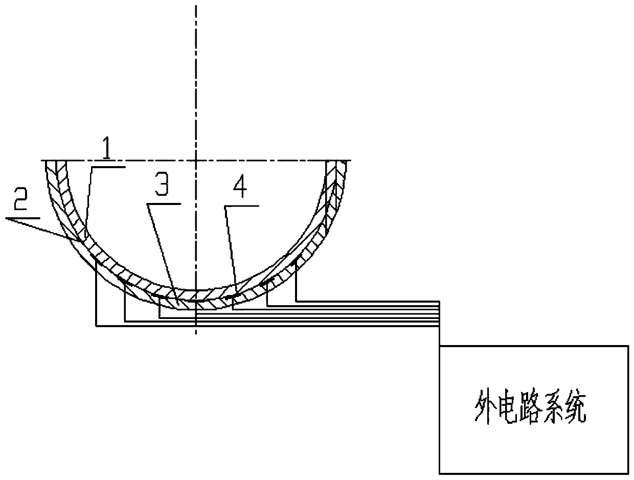
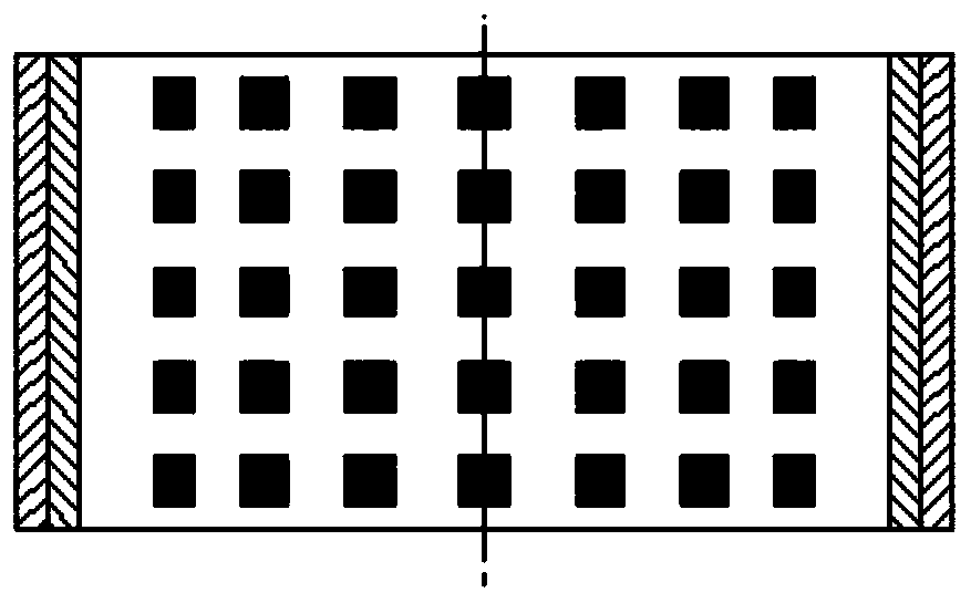
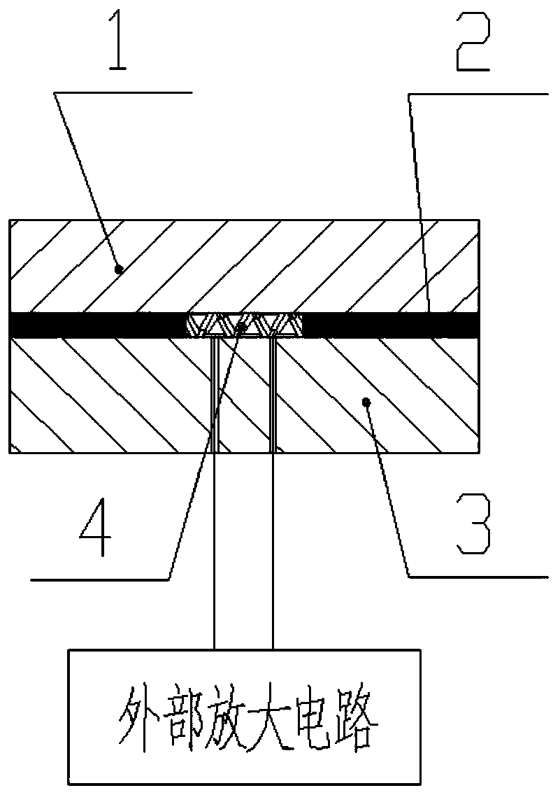
[0018] 1-3d, the present invention is a large-scale bearing bush with integrated pressure sensor, which mainly includes an alloy casting layer 1, a tin-coating layer 2, a rigid back layer 3, a sensor probe 4, and an external circuit.

[0019] Piezoelectric ceramic or Hall element type pressure sensors are integrally cast in the bearing bush, and the finished product can integrate bearing bush lubrication, crankshaft support, oil film pressure measurement, and oil film pressure distribution detection. This product can solve the problem that the oil film pressure cannot be monitored online in real time during the use of bearing products, and the measurement accuracy and accuracy of the conventional oil film pressure measurement method are damaged. A gap in the diagnostics industry.

[0020] This product adopts advanced manufacturing technology and utilizes the char...


PUM


Abstract

The invention aims at providing a large bearing bush integrated with a pressure sensor. The large bearing bush integrated with the pressure sensor comprises an upper bearing bush and a lower bearing bush, wherein an upper rigid rear layer is arranged on the upper bearing bush; an upper tin coating layer is poured on the inner surface of the upper rigid rear layer by a tin coating technology; a lower rigid rear layer is arranged on the lower bearing bush; a sensor probe array is mounted on the inner surface of the lower rigid rear layer; a lower tin coating layer is poured on the inner surfaceof the lower rigid rear layer by the tin coating technology; sensor probes of the sensor probe array are positioned in the lower tin coating layer; alloy layers are centrifugally casted on the upper tin coating layer and the lower tin coating layer; an oil charging hole and an oil channel are formed in the upper bearing bush; a conductor hole is formed in the lower rigid rear layer; outer sensor probe conductors of the sensor probe array are guided out from the lower bearing bush through the conductor hole; and protecting films are adhered to the outer parts of the upper rigid rear layer and the lower rigid rear layer. The large bearing bush integrating the pressure sensor meets the use demands on supporting, lubricating and heavy loading of the bearing bush and is capable of monitoring the pressure level and the pressure distribution modes of an oil film of the bearing bush in running process in real time through a built-in pressure sensor.

Description

technical field [0001] The invention relates to a low-speed diesel engine, in particular to a low-speed diesel engine bearing bush. Background technique [0002] The big-end bearing bush of the connecting rod of high-power marine diesel engine is the most important rotating friction pair in the diesel engine, and its friction loss accounts for more than 20% of the friction loss of the whole diesel engine. One of the heavy parts. Bearing pads have many defects or deficiencies in structural design, product processing, parts installation and debugging, maintenance and testing, etc., which will cause vibration during the operation of the equipment, increased local oil film pressure, increased friction, and intense flashing of lubricating oil The flash impact pressure of the bearing pad can easily cause fatigue pitting and peeling of the alloy layer of the bearing pad, which will seriously affect the service life of the bearing pad and crankshaft, and even cause serious damage a...

Claims


Application Information

Patent Timeline
Patent Type & Authority Applications(China)
IPC IPC(8): F16C33/06G01L9/08G01L9/00
CPCF16C33/06G01L9/08G01L9/00
Inventor 王贵新陈广库李晓波李业鹏钟宁于子宁马金凤纪洪姣
Owner HARBIN ENG UNIV
Learn More