Electric control liquid crystal bionic imaging micromirror, preparation method and optical microscope

An imaging micromirror, liquid crystal technology, applied in microscopes, optics, optical components, etc., can solve the problems of throwing, reducing the amount of imaging data, high and low definition partitions with imaging functions, inability to achieve concentration, etc., achieving high structure, light field and The effect of good target adaptability and high control accuracy

Inactive Publication Date: 2019-07-19
NANJING OPY ELECTRONICS TECH CO LTD
View PDF11 Cites 0 Cited by
  • Summary
  • Abstract
  • Description
  • Claims
  • Application Information

AI Technical Summary

Problems solved by technology

[0003] However, the existing optical microscopic imaging technology has some technical problems that cannot be ignored: First, because it cannot imitate the human eye by physical means through a large-scale densely packed cone and columnar visual cells in the macular area, and the light The signal is converted into a bioelectronic signal and transmitted to the brain through the optic nerve network to form a high-definition image (including red, blue, and green color images of cone cells and colorless gray images of column cells in dark night conditions), so It does not have the imaging function compatible with strong light and low light sensing; second, because it cannot physically imitate the densely packed photosensitive cells based on the macular area of ​​the human eye and the sparsely distributed photosensitive cells outside the macular area, so its It does not have the high-

Method used


Image

  • Electric control liquid crystal bionic imaging micromirror, preparation method and optical microscope
  • Electric control liquid crystal bionic imaging micromirror, preparation method and optical microscope
  • Electric control liquid crystal bionic imaging micromirror, preparation method and optical microscope

Examples


Example Embodiment

[0055] In order to make the object, technical solution and advantages of the present invention clearer, the present invention will be further described in detail below in conjunction with the accompanying drawings and embodiments. It should be understood that the specific embodiments described here are only used to explain the present invention, not to limit the present invention. In addition, the technical features involved in the various embodiments of the present invention described below can be combined with each other as long as they do not constitute a conflict with each other.

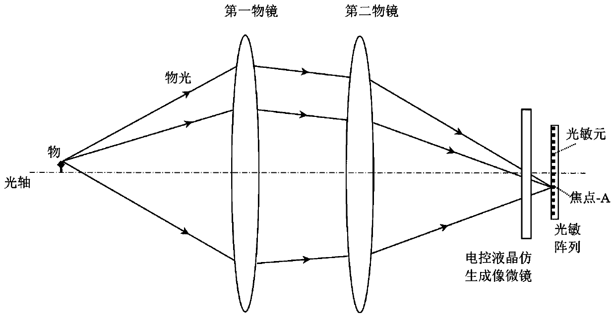
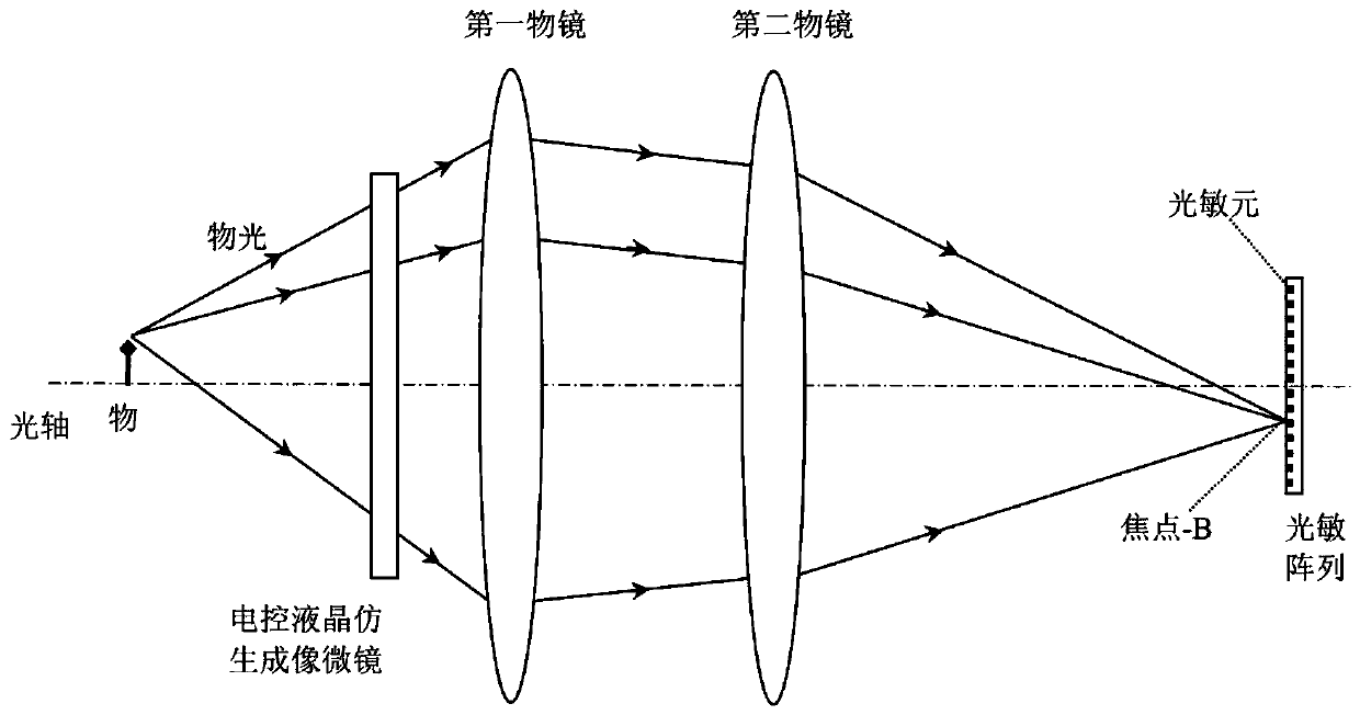
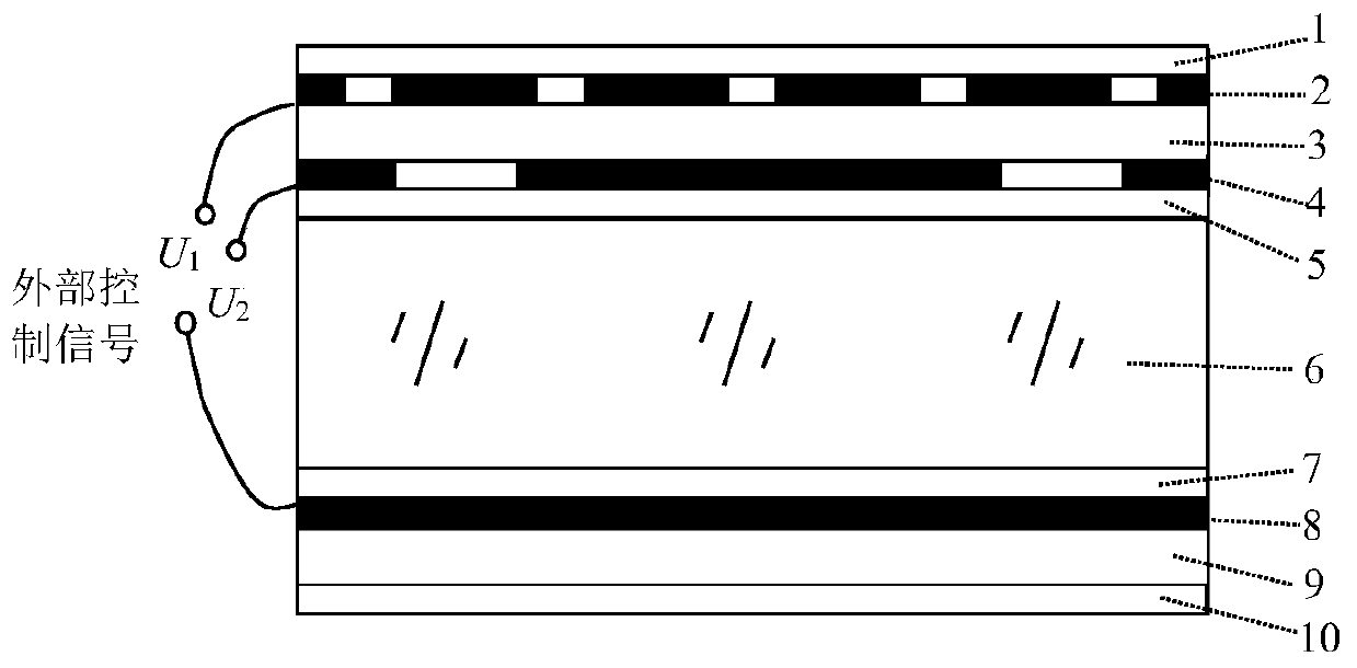
[0056] like image 3 As shown, the electronically controlled liquid crystal imitation imaging micromirror of the present invention includes a first anti-reflection film 1, a first pattern electrode 2, a first substrate 3, a second pattern electrode 4, and a first liquid crystal that are arranged in parallel from top to bottom. Alignment layer 5 , liquid crystal layer 6 , second liquid crystal a...


PUM

PropertyMeasurementUnit
Thicknessaaaaaaaaaa
Thicknessaaaaaaaaaa
Thicknessaaaaaaaaaa

Abstract

The invention discloses an electric control liquid crystal bionic imaging micromirror which comprises a first pattern electrode, a first substrate, a second pattern electrode, a first liquid crystal orientation layer, a liquid crystal layer, a second liquid crystal orientation layer, a common electrode and a second substrate which are sequentially arranged from top to bottom in parallel. A first micro-hole near one end of the first pattern electrode and led out from the first pattern electrode through a electric connection line and another electric connection line led out from the common electrode are respectively connected to two ends of a first external control signal U1. A second micro-hole near one end of the second pattern electrode and led out from the second pattern electrode through a electric connection line and another electric connection line led out from the common electrode are respectively connected to two ends of a second external control signal U2. The imaging micromirror according to the invention can solve the technical problem that the existing imaging micromirrors cannot combine the imaging functions such as bright field and dark field imaging detection, high-definition and low-definition imaging detection, light field and staring imaging detection, light field and conventional plane imaging detection and the like.

Description

technical field [0001] The invention belongs to the technical field of optical microscopic imaging and control, and more specifically relates to an electronically controlled liquid crystal imitation imaging micromirror, a preparation method and an optical microscope. Background technique [0002] Bionics and biological vision research shows that the human eye has formed a unique visual mechanism after long-term evolution, which can efficiently perform controlled collection of light wave energy, block generation of photoelectric signal clusters, cooperative transport of bioelectronic signal neural networks and Brain mapping, image information weighting processing, utilization, feedback calibration and light control, etc. The bionic imaging architecture developed based on the above characteristics of the human eye in collaborative imaging has been widely used in the field of optical imaging technology. [0003] However, the existing optical microscopic imaging technology has ...

Claims


Application Information

Patent Timeline
IPC IPC(8): G02F1/1343G02F1/1333G02F1/1337G02F1/13G03F7/16G03F7/20G02B21/02
CPCG02B21/025G02F1/1303G02F1/1333G02F1/133723G02F1/134309G03F7/16G03F7/168G03F7/2002G02F1/1316
Inventor 张汤安苏张新宇
Owner NANJING OPY ELECTRONICS TECH CO LTD
Why Eureka
Try Eureka