Current commutation H-bridge type hybrid direct current fault current limiter topology
A technology of DC fault and current limiter, which is applied in the direction of emergency protection circuit devices, electrical components, circuit devices, etc. for limiting overcurrent/overvoltage, and can solve the problem of high failure rate on the DC side and half-bridge sub-modules that do not have DC Fault clearing ability and other issues to achieve the effect of suppressing fault current, good economy, and reducing demand
- Summary
- Abstract
- Description
- Claims
- Application Information
AI Technical Summary
Problems solved by technology
Method used
Image

Examples
Embodiment Construction
[0016] The technical solutions in the embodiments of the present application will be clearly and completely described below in conjunction with the drawings in the embodiments of the present application.
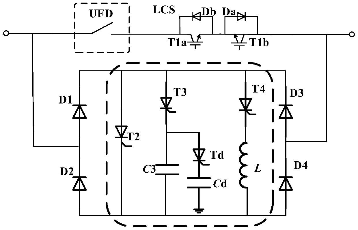
[0017] The topology of the current-commutated H-bridge hybrid DC fault current limiter is as follows: figure 1 As shown, it includes the on-state low-loss branch, the current commutation branch and four groups of H-bridge diodes, wherein the on-state low-loss branch includes ultra-fast mechanical switches and load transfer switches, and the current commutation branch contains three current Transfer branches.
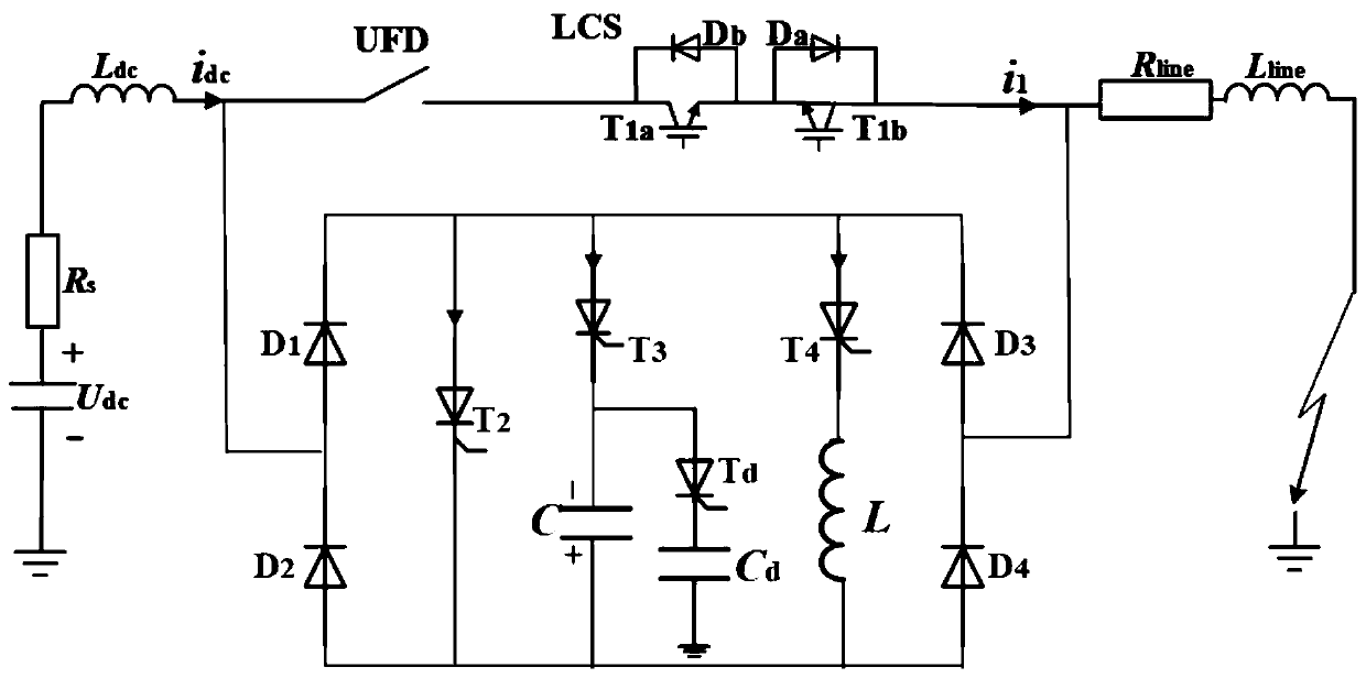
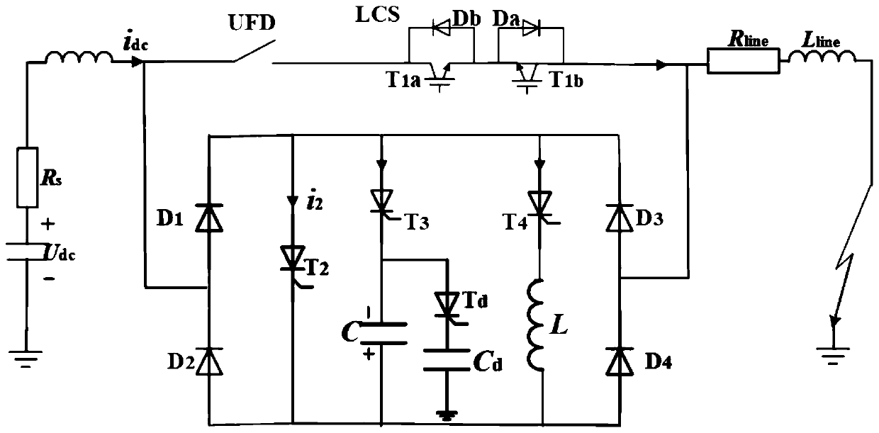
[0018] In order to meet the bidirectional current limiting capability, four H-bridge diode groups are connected in parallel on both sides of the current commutation branch. Under normal circumstances, the line current flows from left to right. When a ground fault occurs on the right side of the current limiter, the fault current flows from left to right to the fault ...
PUM
 Abstract
Description
Claims
Application Information
 - Generate Ideas
- Intellectual Property
- Life Sciences
- Materials
- Tech Scout
- Unparalleled Data Quality
- Higher Quality Content
- 60% Fewer Hallucinations
Browse by: Latest US Patents, China's latest patents, Technical Efficacy Thesaurus, Application Domain, Technology Topic, Popular Technical Reports.
© 2025 PatSnap. All rights reserved.Legal|Privacy policy|Modern Slavery Act Transparency Statement|Sitemap|About US| Contact US: help@patsnap.com