Carbon nanotube array thruster

A carbon nanotube array and carbon nanotube technology, which is applied in the direction of thrust reverser, machine/engine, and plasma utilization, can solve the problems affecting the service life of the system and the hazards of the spacecraft, and achieve a high degree of adjustment freedom and reduce The effect of volume and mass

Inactive Publication Date: 2019-07-26
DALIAN UNIV OF TECH
View PDF7 Cites 5 Cited by
  • Summary
  • Abstract
  • Description
  • Claims
  • Application Information

AI Technical Summary

Problems solved by technology

[0003] When the ion thruster is working, the tail of the thruster will eject a high-speed ion flow, which will form a high potential around the electric propulsion system, which will cause certain harm to the spacecraft and affect the service life of the system

Method used


Image

  • Carbon nanotube array thruster

Examples


Embodiment Construction

[0020] In order to clarify the purpose, technical solutions and advantages of the embodiments of the present invention more clearly, the technical solutions in the embodiments of the present invention will be clearly and completely described below in conjunction with the drawings in the embodiments of the present invention. Obviously, the described embodiments are some, but not all, embodiments of the present invention. Based on the embodiments of the present invention, all other embodiments obtained by persons of ordinary skill in the art without creative work belong to the protection scope of the present invention

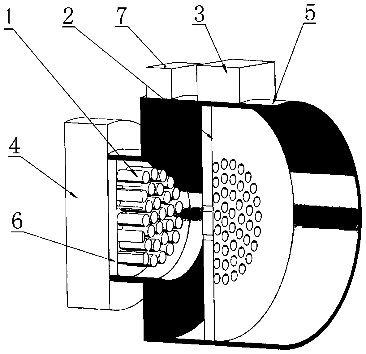
[0021] figure 1 It is a schematic cross-sectional structure diagram of a carbon nanotube array thruster in the present invention. This embodiment may include: a carbon nanotube array thruster, including a carbon nanotube unit array 1, a metal grid 2, a power supply 3, and a working fluid storage Box 4 , protective layer 5 , fixing plate 6 , microprocessing eleme...


PUM


Abstract

The invention discloses a carbon nanotube array thruster, and belongs to the technical field of space propulsion. The carbon nanotube array thruster comprises a carbon nanotube unit array, a metal grid electrode, a power supply, a working medium storage box, a protective layer, a fixing plate and a micro-treatment element, wherein the protective layer comprises a front portion and a rear portion,the middle of the front portion and the middle of the rear portion are connected in a communicating mode, the fixing plate is arranged at the front end of the front half portion, the carbon nanotube unit array is distributed on one side of the fixing plate in an array mode, the working medium storage box is arranged on the other side of the fixing plate, the micro-treatment element and the power supply are arranged above the outer surface of the rear half portion, the metal grid electrode is round and is fixed in the rear half portion of the protective layer, when the thruster works, the carbon nanotube unit array is electrified, an argon working medium enters the carbon nanotube unit array from the working medium storage box through the fixing plate, the micro-treatment element controls the working mode of the carbon nanotube unit array, and controls the potential of the metal grid electrode to correspond to the working mode of the carbon nanotube unit array, so that the two working states are achieved. According to the carbon nanotube array thruster, the performance parameters of the thruster can be precisely adjusted, and the size and the mass of the thruster can be effectivelyreduced.

Description

technical field [0001] The invention belongs to the field of space propulsion technology, and relates to a carbon nanotube array thruster. Background technique [0002] Carbon nanotubes (CNTs) are one-dimensional nanomaterials with a special structure. Carbon nanotubes have some excellent properties and have huge potential applications. Compared with the traditional thermal emission cathode system, carbon nanotube field emission has the advantages of low power consumption, high current density, small size, and high efficiency, and is an ideal new vacuum electron emission source. At the same time, carbon nanotubes can be used as ionization devices. At present, there are two main design ideas for carbon nanotube ionization sources, impact ionization and field ionization. The main characteristics of the carbon nanotube ionization device are small excitation voltage and large current generation, which have certain advantages compared with traditional ionization devices. [00...

Claims


Application Information

Patent Timeline
Patent Type & Authority Applications(China)
IPC IPC(8): F03H1/00
CPCF03H1/00
Inventor 郭明坤夏广庆孙斌韩亚杰范益朋关思琦
Owner DALIAN UNIV OF TECH
Why Eureka
Try Eureka