
Bellows stem assembly for high frequency quick opening valve

A technology for bellows valves and bellows sections, applied in the direction of threaded fasteners, valve devices, valve details, etc., can solve the problems of increasing the frequency of bellows replacement, cracking failure, fatigue failure of bellows valve stem components, etc.

Active Publication Date: 2020-07-07
HEFEI GENERAL MACHINERY RES INST
View PDF5 Cites 0 Cited by
  • Summary
  • Abstract
  • Description
  • Claims
  • Application Information

AI Technical Summary

Problems solved by technology

[0004] The pulse blowback valve uses the bellows valve stem assembly to complete a round of action in a very short time, and the entire bellows valve stem is longer, so the main deformation of the bellows is concentrated at the adjacent welded joint between the bellows and the valve stem. The wave band, that is, the tension and compression deformation of the bellows section exceeds the design average value, and it first reaches the fatigue limit, and then cracks and fails, resulting in fatigue failure of the entire bellows valve stem assembly, increasing the replacement frequency of the bellows

Method used


Image

  • Bellows stem assembly for high frequency quick opening valve
  • Bellows stem assembly for high frequency quick opening valve
  • Bellows stem assembly for high frequency quick opening valve

Examples


Embodiment 1

[0049] Such as image 3As shown, the valve rod 1 includes a shaft, an installation guide groove 1g provided in the axial direction of the shaft, and an annular limit groove 1f provided on the shaft body. The two ends of the shaft are respectively provided with a connecting section 1j of a driving device and a boss 1d. The boss 1d is sequentially connected with the disc installation section 1c, the lock nut installation section 1b and the guide section 1a. The disc installation section 1c is provided with left-handed threads; the lock nut installation section 1b is provided with right-hand threads, that is, the threads of the valve disc installation section 1c and the lock nut installation section 1b are in the opposite direction of rotation. An annular general limit groove 1h is opened on the shaft adjacent to the connecting section 1j of the driving device.

Embodiment 2

[0051] On the basis of Example 1, such as figure 1 As shown, a special bellows valve stem assembly for high-frequency quick-opening valves includes a valve stem 1, the valve stem 1 is covered with a bellows 2, and the bellows 2 includes several bellows sections arranged in sequence along the axial direction of the valve stem 1, several The bellows section is located between the boss 1d and the fixed flange 4, and the adjacent bellows sections are connected by the connecting ring 3 sleeved on the valve stem 1, and the connecting ring 3 is movably arranged in the annular limit groove 1f opened by the valve stem 1 Inside, the height of the annular limiting groove 1f is smaller than the maximum allowable deformation of the section of the bellows it limits, and the connecting ring 3 and the annular limiting groove 1f cooperate with each other to deform each section of the bellows.

[0052] From the boss 1d to the side of the fixed flange 4, the adjacent annular limiting grooves 1f ...

Embodiment 3

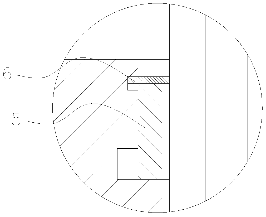
[0061] On the basis of Example 1 and Example 2, as Figure 5 and Figure 5B As shown, there are several raised connecting ring stoppers 3a on the mating surface between the connecting ring 3 and the valve stem 1, and the valve stem 1 is provided with an installation guide groove 1g along the axial direction, and the width of the connecting ring stopper 3a is slightly smaller than The width of the installation guide groove 1g, the connecting ring limit portion 3a and the annular limit groove 1f form a clearance fit, and the connection ring limit portion 3a is staggered by a certain angle around the axis of the valve stem 1 and the installation guide groove 1g.

[0062] In this embodiment, the installation guide groove 1g may also run through the entire valve stem 1 . Such as Figure 3A As shown, the installation guide groove 1g can be a keyway type guide groove 1k, such as Figure 3B As shown, the installation guide groove 1g can also be an arc bottom type guide groove 1m. ...


PUM


Abstract

The invention relates to the field of valves, in particular to a corrugated tube valve rod assembly special for a high-frequency quick-opening valve. The corrugated tube valve rod assembly special forthe high-frequency quick-opening valve comprises a valve rod. A boss and a fixed flange are arranged on the valve rod. A corrugated tube is arranged on the outer portion of the valve rod in a sleeving manner. The corrugated tube comprises multiple corrugated tube segments sequentially arranged in the axial direction of the valve rod. The multiple corrugated tube segments are located between the boss and the fixed flange. The adjacent corrugated tube segments are connected through connecting rings arranged on the valve rod in a sleeving manner. The connecting rings are movably arranged in annular limiting grooves formed in the valve rod. The height of the annular limiting grooves is smaller than the maximum allowable deformation of the corrugated pipe segments limited by the annular limiting grooves. The multiple limiting grooves and the connecting rings arranged on the valve rod cooperate with each other, it can be guaranteed that when the corrugated tube valve rod assembly does high-frequency rapid reciprocating action, the stretching quantity or compression quantity of the segments, close to the boss and the flange, of the corrugated tube is small, the situation that deformationof the whole corrugated tube is only concentrated on the two segments of the corrugated tube is avoided, and then the situation that fatigue failures happen too early due to the fact that local corrugated tube deformation is too large is avoided.

Description

technical field [0001] The invention relates to the field of valves, in particular to a special bellows valve stem assembly for high-frequency quick-opening valves. Background technique [0002] In the process industry or the aerospace industry, in order to meet the high-frequency and fast-response valve process requirements, quick-opening valves with bellows valve stem components are generally used. Since the valve stem seal is directly realized by the bellows, no packing seal is provided, so It can meet the high frequency and fast response requirements of the valve. [0003] In the Shell pulverized coal gasification process, the syngas needs to pass through a high-temperature and high-pressure ceramic filter for dry ash removal. In order to realize the blowback cleaning of the filter element, it is necessary to provide a pulse blowback valve to generate a pulsed air flow to reversely clean the filter cake attached to the filter element. When the pulse blowback valve is w...

Claims


Application Information

Patent Timeline
Patent Type & Authority Patents(China)
IPC IPC(8): F16K41/10F16K47/00F16B39/02B01D46/00
CPCB01D46/00F16B39/02F16K41/10F16K47/00
Inventor 陈凤官王渭明友王勤吴怀昆余宏兵耿圣陶高红彪叶晓节杨玲玲
Owner HEFEI GENERAL MACHINERY RES INST
Learn More