
Low resonance eccentric fiber optic acoustic sensor based on F-P interference

A sensing device, F-P technology, which is applied in measurement devices, ultrasonic/sonic/infrasonic waves, instruments, etc., can solve the problems of long echo duration, limited application scenarios, strong resonance, etc., and achieve high sensitivity and high measurement accuracy. , the effect of reducing after-vibration

Inactive Publication Date: 2019-07-26
BEIHANG UNIV
View PDF6 Cites 5 Cited by
  • Summary
  • Abstract
  • Description
  • Claims
  • Application Information

AI Technical Summary

Problems solved by technology

The Michelson interferometric optical fiber acoustic sensor has a relatively simple structure, but it is easily affected by external factors when light is transmitted and interfered in multiple optical fibers, which limits its accuracy and application environment.
Mach-Zehnder interference optical fiber acoustic sensor has a large detection bandwidth, but it has the disadvantage of poor stability
Sagnac interferometric fiber optic acoustic sensor has high stability, but it is generally used in the measurement of angular velocity, and the application scenarios are relatively limited
Among the interferometric acoustic sensors, the optical fiber acoustic sensor based on F-P interference has attracted much attention because of its high precision, small size and high stability, but this kind of sensor has strong resonance and long reverberation duration, which is often can cause loud noise

Method used


Image

  • Low resonance eccentric fiber optic acoustic sensor based on F-P interference
  • Low resonance eccentric fiber optic acoustic sensor based on F-P interference
  • Low resonance eccentric fiber optic acoustic sensor based on F-P interference

Examples


Embodiment Construction

[0021] The technical solutions in the embodiments of the present invention will be clearly and completely described below with reference to the accompanying drawings in the embodiments of the present invention. Obviously, the described embodiments are only a part of the embodiments of the present invention, not all of the embodiments. Based on the embodiments of the present invention, all other embodiments obtained by those of ordinary skill in the art without creative efforts shall fall within the protection scope of the present invention.

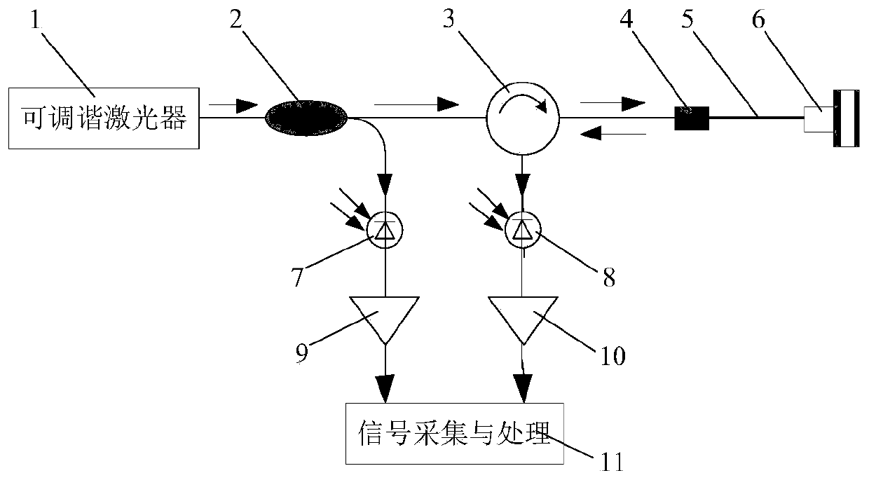
[0022] figure 1 Shown is a schematic diagram of the optical path of the eccentric optical fiber acoustic sensing device in this embodiment. The eccentric optical fiber acoustic sensing device in this embodiment includes a tunable laser module 1, an optical fiber coupler 2, an optical fiber circulator 3, a single-mode optical fiber eccentric optical fiber module 4, an eccentric optical fiber acoustic sensing head 6, an eccentric optical fi...


PUM

PropertyMeasurementUnit
Thicknessaaaaaaaaaa
Thicknessaaaaaaaaaa

Abstract

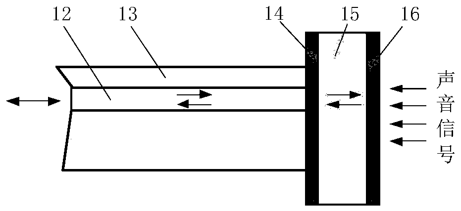
The invention provides a low resonance eccentric fiber optic acoustic sensor based on F-P interference. The device comprises the following contents that the laser emitted by a tunable laser is dividedinto two paths after passing through a fiber optic coupler, one path is directly collected as reference light and the other path enters an eccentric fiber optic acoustic sensor head through a fiber optic circulator and a single-mode fiber optic to eccentric fiber optic module, and the reflected light enters the other photoelectric conversion module through the fiber optic circulator. The eccentric fiber optic acoustic sensor head coats a transparent organic molecular film and two metal films on the eccentric fiber optic end surface by a coating technology to form an F-P resonant cavity, and the F-P interference generated at the front end of the fiber optic through by the light can be used to convert the sound signal into a modulated optical signal. After passing through the photoelectricconversion module and the amplification module, the signal is collected and processed to restore the acoustic signal at the fiber optic end. The design of the eccentric fiber optic greatly reduces resonance and residual vibration noises. The low resonance eccentric fiber optic acoustic sensor based on F-P interference provided by the invention has the advantages of simple structure, good reliability, higher sensitivity and signal-to-noise ratio than the traditional fiber optic sensor, and has wide application prospects.

Description

[0001] (1) Technical field [0002] The invention relates to a low-resonance eccentric optical fiber acoustic sensing device based on F-P interference. Specifically, the F-P optical interference is used to design and manufacture an eccentric optical fiber acoustic sensor, which can obtain pressure signal detection with low resonance, high precision and high resolution. [0003] (2) Background technology [0004] Acoustic detection technology is a technology that understands the internal information of the medium by detecting the changes in the speed, frequency and amplitude of the echoes reflected in the medium. It can detect living organisms or raw materials in a non-destructive state, and is widely used in biomedicine. , aerospace and other fields. The key of acoustic wave detection technology is acoustic sensor, but so far, traditional acoustic sensor generally uses piezoelectric material to collect vibration information, which has disadvantages such as low sensitivity and l...

Claims


Application Information

Patent Timeline
IPC IPC(8): G01H9/00
CPCG01H9/004
Inventor 马建国徐立军马向东付博
Owner BEIHANG UNIV
Learn More