Flow distribution sliding disc pair and plunger pump or motor comprising structure
A technology of distribution plate and sliding plate, which is applied in the direction of plunger, parts of pumping device for elastic fluid, pump, etc., which can solve the problem of increased failure probability of pump or motor, slow variable response time, increased pump volume loss, etc. problem, to achieve the effect of improving the power density per unit mass, fast variable response speed, and reducing cylinder overturning
- Summary
- Abstract
- Description
- Claims
- Application Information
AI Technical Summary
Problems solved by technology
Method used
Image
Examples
Embodiment 1
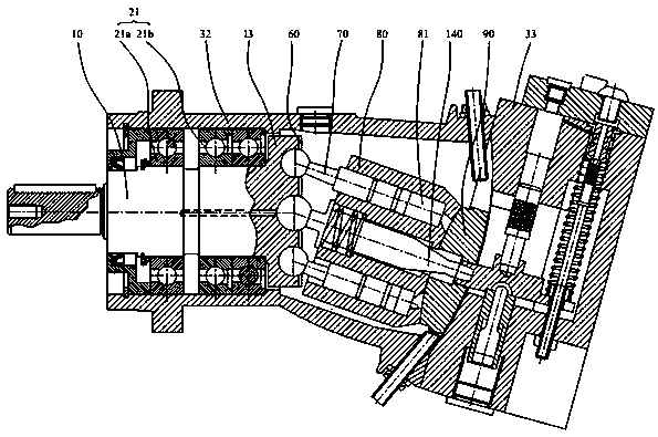
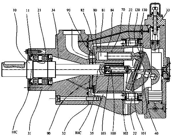
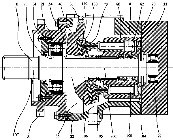
[0049] like Figure 4-11 Shown is an embodiment of the distribution slide plate pair of the present invention and the plunger pump including the structure. In the preferred embodiment shown, the plunger pump is a non-through-shaft plunger pump, including a main shaft 10, Housing, first bearing 21, swash plate 40, slide plate 50, plunger 70 and cylinder 80, the main shaft axis 10C of the main shaft 10 coincides with the cylinder central axis 80C of the cylinder 80, the One end of the main shaft 10 extends out of the shell and is supported on the first bearing 21, and the other end cantilever supports the cylinder body 80 and is connected with the cylinder body 80 through a key. The static pressure bearing surface 51 of the sliding plate 50 is supported on the swash plate 40, And keep closely fit with the support surface of the swash plate 40, one end of the sliding plate 50 is provided with a plurality of waist-shaped oil chambers 53a, and the other end surface of the sliding p...
Embodiment 2
[0067] Such as Figure 16 with 17 As shown, the main difference from other embodiments is that the axial piston pump or motor of this embodiment is a through-shaft piston pump or motor. The through-shaft axial piston pump includes a main shaft 10, a housing, a first bearing 21, a second bearing 22, a swash plate 40, a sliding plate 50, a plunger 70 and a cylinder block 80. The main shaft axis of the main shaft 10 10C coincides with the central axis 80C of the cylinder body 80, one end of the main shaft 10 is supported on the first bearing 21, and the other end is supported on the second bearing 22, and the main shaft 10 and the cylinder body 80 are synchronized through a key connection Rotate, the cylinder block 80 is supported in the central area of the main shaft 10, from the coupling end of the main shaft 10 to the end cover direction, the main shaft 10 runs through the cylinder block 80, the pressure plate 60, the sliding plate 50 and the swash plate 40 in sequence; the...
Embodiment 3
[0071] Such as Figure 14 with 15 As shown, the main difference from other embodiments is that a flow distribution plate 90 is interposed between the sliding plate 50 and the swash plate 40 in the sliding plate pair, and the sliding plate 51 is supported on the flow distribution plate 90 and keeps sliding with the flow distribution plate 90 Cooperate, the distribution plate is fixed on the swash plate by means of pins, etc., and the distribution plate 90 is provided with a high-pressure distribution window 93 and a low-pressure distribution window 92, such as Figure 14As shown, the high-pressure distribution window 93 and the low-pressure distribution window 92 communicate with the waist-shaped low-pressure distribution window 43 and the waist-shaped high-pressure distribution window 44 on the swash plate respectively. The low-pressure distribution window 92 and the high-pressure distribution window 93 can be arranged in a symmetrical or asymmetrical structure relative to th...
PUM
 Abstract
Description
Claims
Application Information
 - R&D
- Intellectual Property
- Life Sciences
- Materials
- Tech Scout
- Unparalleled Data Quality
- Higher Quality Content
- 60% Fewer Hallucinations
Browse by: Latest US Patents, China's latest patents, Technical Efficacy Thesaurus, Application Domain, Technology Topic, Popular Technical Reports.
© 2025 PatSnap. All rights reserved.Legal|Privacy policy|Modern Slavery Act Transparency Statement|Sitemap|About US| Contact US: help@patsnap.com


