
Optical fiber remote centralized timing system and timing method based on BD and GPS

A time service system and optical fiber remote technology, applied to radio-controlled timers, instruments, etc., can solve the problems of RF feeders reducing the flexibility of BBU machine room location selection, increasing construction difficulty and maintenance costs, and the flexibility of RF feeders. , to facilitate the understanding of signal conditions, solve engineering construction difficulties, and improve safety

Active Publication Date: 2019-07-30
NANJING HOWSO TECH +1
View PDF7 Cites 11 Cited by
  • Summary
  • Abstract
  • Description
  • Claims
  • Application Information

AI Technical Summary

Problems solved by technology

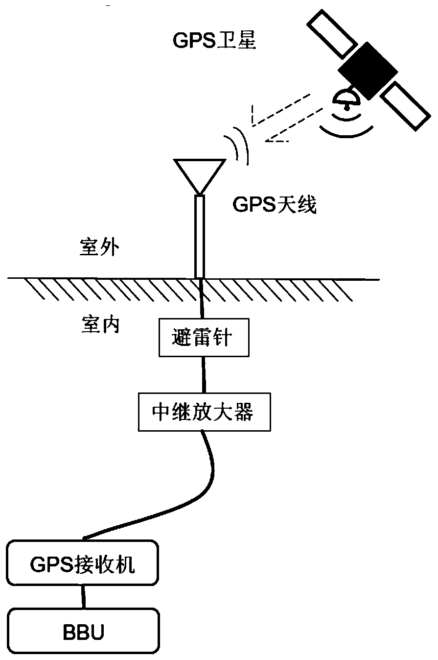
The antenna is connected to the receiver on the BBU side of the base station through a radio frequency feeder. The radio frequency feeder is thick and has poor flexibility and is not easy to bend. The signal attenuates quickly, and a line compensation amplifier is required for long-distance transmission.
The characteristics of RF feeders reduce the flexibility of BBU equipment room location selection, increasing construction difficulty and maintenance costs, such as figure 1 shown
In addition, GPS is an important infrastructure for the US military to realize its strategic and tactical intentions. Under exceptional circumstances, once the system is shut down or interfered with, the communication system will be paralyzed, posing a huge security risk

Method used


Image

  • Optical fiber remote centralized timing system and timing method based on BD and GPS
  • Optical fiber remote centralized timing system and timing method based on BD and GPS
  • Optical fiber remote centralized timing system and timing method based on BD and GPS

Examples


Embodiment

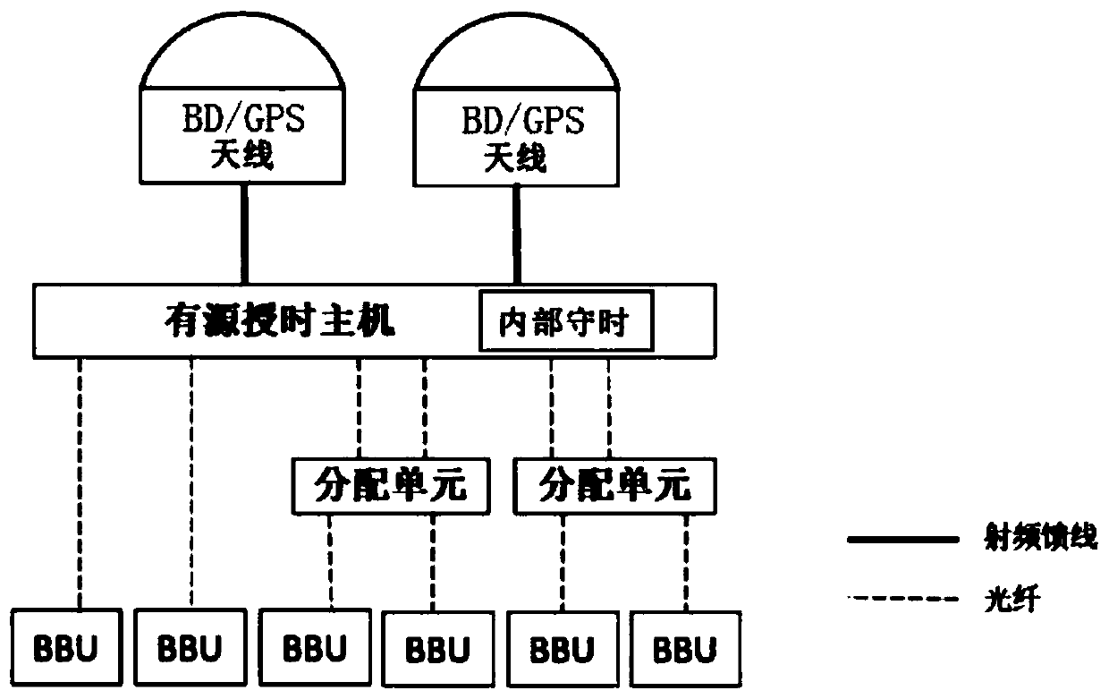
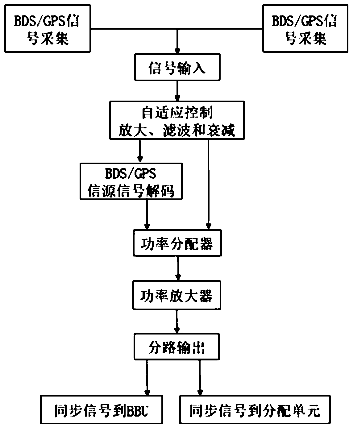
[0031] Example: such as figure 2 As shown, the BD and GPS-based remote fiber optic remote centralized timing system includes two BD / GPS antennas, an active timing host, and at least one active timing distribution unit. The Beidou satellite navigation system BD antenna and global positioning system GPS antennas are all connected to the active timing host, which is connected to the active timing distribution unit or / and the baseband processing unit BBU; the active timing host includes a CPU control module Channel input module, adaptive control amplification filtering and attenuation module, clock source module, BD / GPS source signal decoding module, branch output module and power management module one; the CPU control module one is used to send control hardware to other modules Setting and information processing control information; the branch input module is used to receive the satellite signal from the satellite antenna; the adaptive control amplifying filter and attenuation mod...


PUM


Abstract

The present invention discloses an optical fiber remote centralized timing system and method based on BD and GPS. The system comprises at least one satellite antenna, an active timing host and at least one active timing distribution unit. The satellite antenna is connected with the active timing host. The optical fiber remote centralized timing system based on BD and GPS is composed of a BD / GPS antenna, 1+1 primary and secondary units and the distribution unit, so as to improve accuracy and safety of base station timing. A photoelectric hybrid cable is adopted for transmission, which can transmit at least one kilometer. An optical fiber can be stretched to 20 kilometers if a manner of taking nearest electricity is adopted, thereby fundamentally solving the problem of affecting a base station location due to the limited transmission distance.

Description

Technical field [0001] The invention belongs to the technical field of the mobile communication industry, and particularly relates to a BD and GPS-based optical fiber remote centralized time service system and a time service method. Background technique [0002] Timing refers to the equipment in the communication network that obtains a unified clock source signal to achieve synchronization between network devices. The current mobile communication network generally uses satellite on-board clocks as the clock source. The Global Positioning System (GPS) in the United States and the BeiDou Navigation Satellite System (BDS) in China have the ability to provide time for mobile communication networks. [0003] At present, most of the base stations operating on the network in China use a single GPS satellite clock as a clock source, and use traditional GPS time service antennas to obtain clock signals and transmit them to the baseband processing unit (hereinafter referred to as BBU) of the...

Claims


Application Information

Patent Timeline
Patent Type & Authority Applications(China)
IPC IPC(8): G04R20/02
CPCG04R20/02
Inventor 梁泉许科奎王计斌
Owner NANJING HOWSO TECH
Learn More