
Vertical pre-perforation device in cubic original rock sample borehole and pre-perforation processing method

A technology in a cube and a borehole, which is applied to the vertical pre-perforation device and the pre-perforation processing field in the borehole of the original rock sample of the cube, and can solve the problems of difficulty in making the original rock sample and the like.

Inactive Publication Date: 2019-08-06
CHONGQING UNIV
View PDF7 Cites 2 Cited by
  • Summary
  • Abstract
  • Description
  • Claims
  • Application Information

AI Technical Summary

Problems solved by technology

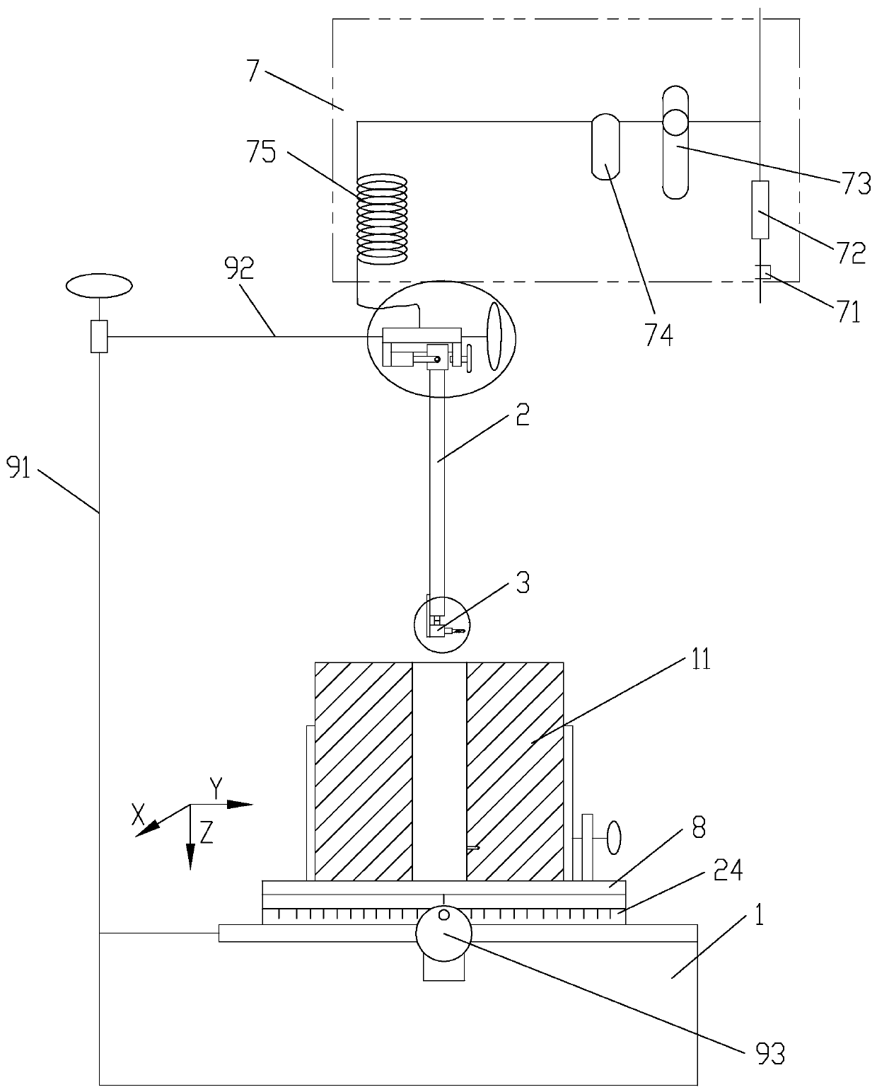
[0007] The first purpose of the present invention is to provide a vertical pre-perforation device in the borehole of the cube original rock sample to solve the deficiency of using simulated similar materials to make the sample in the multi-stage fracturing experiment in the prior art, so as to pass through the device in the original rock Pre-perforation is carried out in sample drilling to solve the difficult problem of making original rock samples

Method used


Image

  • Vertical pre-perforation device in cubic original rock sample borehole and pre-perforation processing method
  • Vertical pre-perforation device in cubic original rock sample borehole and pre-perforation processing method
  • Vertical pre-perforation device in cubic original rock sample borehole and pre-perforation processing method

Examples


Embodiment 1

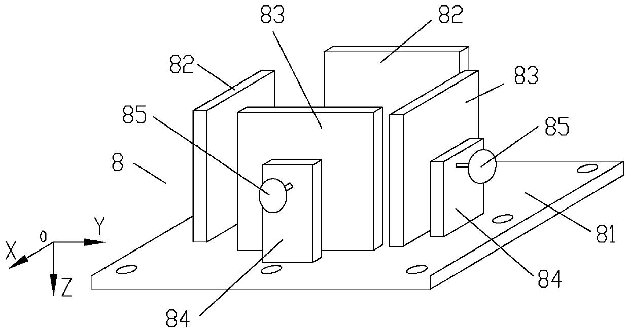
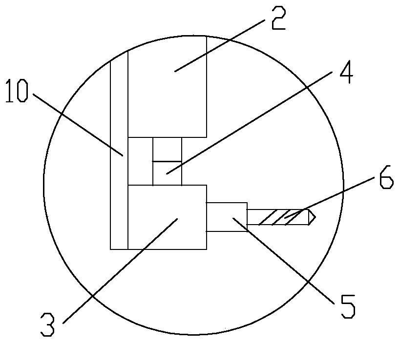
[0047] Example 1, see figure 1 , figure 2 , image 3 , Figure 4 , a vertical pre-perforation device in a cube original rock sample borehole, comprising a base platform 1, an air drill, a sample holder 8, an air pressure control device 7 and a position adjustment device; the air drill and the sample holder All devices 8 are connected to the base platform 1 through a position adjustment device; the sample holder 8 is set on the base platform 1 so that it can move horizontally and laterally; the air drill can be vertically lifted and horizontally moved The ground is arranged above the base platform 1; the air drill is also connected with a pressure gas source through the air pressure control device 7; The output end of the pneumatic motor 2 is connected with a right-angle steering transmission device 3, and the housing of the right-angle steering transmission device 3 and the housing of the miniature pneumatic motor 2 are connected through a connecting block 10 to form a rel...

Embodiment 2

[0052] Example 2, combined with figure 1 , figure 2 , image 3 , Figure 4 , a vertical pre-perforation processing method in the borehole of a cubic protorock sample, implemented based on the device of embodiment 1, comprising the steps of:

[0053] The first step is to determine the perforation diameter of the vertical perforation in the through hole in the middle of the cube rough sample, and select the drill bit in the diamond tool 6 of the same diameter, and fix the drill bit on the drill rod 5 by clamping;

[0054] In the second step, fix the prefabricated 300mm × 300mm × 300mm cubic protorock sample 11 with a through hole formed in the middle part on the sample holder 8 according to the vertical mode of the central through hole axis of the sample, and The position of the sample is roughly adjusted by the position adjustment device, so that the central axis of the through hole in the upper middle of the cubic protorock sample 11 is basically located on the axis moving...

Embodiment 3

[0065] Embodiment 3, a vertical pre-perforation processing method in the drilling hole of a cubic proto-rock sample, the difference between this method and embodiment 2 is that the pre-perforation section trimming is performed in the following steps: S21 in the cubic proto-rock of the seventh step After the pre-perforation at different heights in any of the same phases in the upper middle of the sample 11 is completed, the drill bit is lifted above the cubic original rock sample, and the drill bit is replaced with a grinding head; S22 repeats the fifth and sixth steps The first step is to modify the shape of the pre-perforation sections at different heights in the same phase in sequence; S23 retreats the air drill and lifts it above the cubic original rock sample 11 to prepare for the next group of pre-perforation drillers. pieces.


PUM

PropertyMeasurementUnit
diameteraaaaaaaaaa

Abstract

The invention discloses a vertical pre-perforation device in a cubic original rock sample borehole and a pre-perforation processing method. The pre-perforation device comprises a base platform, a gasdrill, a sample holder, an air pressure control device and position adjustment devices. The gas drill and the sample holder are connected to the base platform through three axially adjustable positionadjustment devices. The gas drill is connected to a pressure gas source through the air pressure control device. The gas drill comprises a rod-shaped miniature pneumatic machine whose cross section is smaller than a middle through hole section of a sample and a right angle turning transmission device. The gas drill outputs rotational power through an output end of the right angle turning transmission device and has a diamond tool mounting structure for drilling and shaping. The processing method is implemented based on the pre-perforation device. The device and the method have advantages thatthe device has a simple structure and compact layout, perforation operation becomes convenient, and an original stone sample perforation requirement can be fully satisfied; and a technology process of the processing method is reasonable, operation is convenient and efficiency is high.

Description

technical field [0001] The invention belongs to unconventional oil and gas exploitation simulation technology, in particular to a vertical pre-perforation device and a pre-perforation processing method in a cube original rock sample drilling hole. Background technique [0002] In the fields of unconventional oil and gas exploitation and geothermal energy utilization, such as low-permeability shale oil exploitation, low-permeability shale gas exploitation, deep low-permeability coalbed methane exploitation, and deep dry hot rock development, fluids (water, carbon dioxide, super Critical carbon dioxide, nitrogen, etc.) fracturing technology, as an indispensable and important reservoir permeability enhancement technology for the development of these reservoirs, has attracted extensive attention in the industry in recent years. [0003] In fact, only for hydraulic fracturing technology, scholars have gradually matured the research on the fluid-solid coupling behavior in the proc...

Claims


Application Information

Patent Timeline
Patent Type & Authority Applications(China)
IPC IPC(8): G01N1/28
CPCG01N1/286G01N2001/2873
Inventor 尹光志吴明洋邓博知张东明鲁俊高恒李铭辉王维忠宋真龙赵宏刚刘超刘淑敏
Owner CHONGQING UNIV
Learn More