A Radiation Hardened Outboard Orthogonal Bridge for Aerospace Vehicles

An anti-radiation reinforcement and aircraft technology, applied in the fields of aviation and aerospace communications, can solve problems such as inability to apply aerospace vehicles, inability to meet the requirements of aerospace appearance and size, and inability to apply, and achieve the effect of improving anti-irradiation capabilities.

Active Publication Date: 2022-01-21
SOUTHWEST INST OF APPLIED MAGNETICS
View PDF9 Cites 0 Cited by
  • Summary
  • Abstract
  • Description
  • Claims
  • Application Information

AI Technical Summary

Problems solved by technology

[0004] The existing problems in the structure of the orthogonal bridge designed and manufactured by traditional methods include: (1) the existing orthogonal bridge uses air as the medium, but there is no air medium in the outer space environment, so it cannot be used; (2) the existing orthogonal bridge The use of magnetic materials cannot be applied to environments below -100°C (even to -150°C), and it cannot be applied to aerospace vehicles; (3) the existing orthogonal bridges use dielectric materials, due to the radiation sensitivity of dielectric materials (occurrence degradation, etc.) cannot be used in the space irradiation environment for a long time
[0005] In order to solve the above problems, it is necessary to strengthen the shielding of the dielectric material by radiation, and the existing problems of the strengthening method are as follows: Thicken the shell thickness (>10mm); this method leads to a large increase in the volume of the orthogonal bridge, which cannot meet the aerospace requirements for shape and size;
[0006] Heavy metals such as lead are used for reinforcement; the use of heavy metals such as lead increases the weight and cannot meet the weight requirements of aerospace, and because heavy metals such as lead have poor processability, this is due to the high softness and ductility of lead materials. Low strength, unable to process special-shaped surfaces; that is, low degree of freedom in design;
[0007] The traditional reinforcement method focuses on the particle radiation of the total dose effect, and does not involve the radiation reinforcement of the radiation environment caused by "electromagnetic" such as solar electromagnetic radiation and magnetic storms.

Method used


Image

  • A Radiation Hardened Outboard Orthogonal Bridge for Aerospace Vehicles
  • A Radiation Hardened Outboard Orthogonal Bridge for Aerospace Vehicles
  • A Radiation Hardened Outboard Orthogonal Bridge for Aerospace Vehicles

Examples


Embodiment

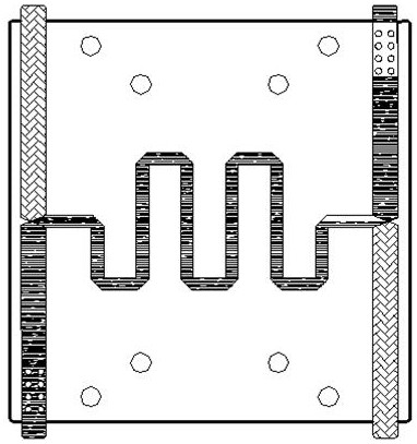
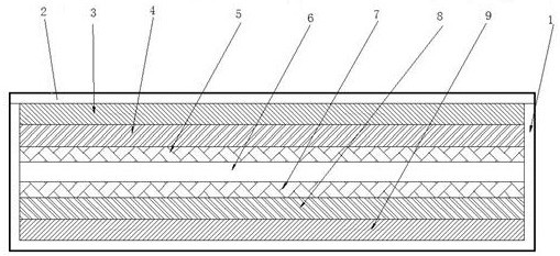
[0022] see figure 2 , a kind of anti-radiation reinforced aerospace vehicle exterior orthogonal bridge, comprising a cavity 1, an orthogonal bridge circuit in the cavity 1 and a cover plate 2 on the top of the cavity, the orthogonal bridge The bridge circuit includes an upper stainless steel plate 3, an upper lead plate 4, a top circuit board 5, a central circuit board 6, a bottom circuit board 7, a lower lead plate 8 and a lower stainless steel plate 9, and the above components are symmetrical with the center circuit board 6 as the center. arrangement;

[0023] In this embodiment, the thicknesses of the upper stainless steel plate 3 and the lower stainless steel plate 9 are the same, both being 0.5mm;

[0024] The thickness of the upper lead plate 4 is the same as that of the lower lead plate 8, which is 0.1mm;

[0025] The cavity 1 and the cover plate 2 are both made of aluminum, with a thickness of 4.0mm;

[0026] The circuit materials, that is, the top circuit board 5 ...

Embodiment 2

[0031] In this example,

[0032] The upper stainless steel plate 3 has the same thickness as the lower stainless steel plate 9, which is 0.5mm;

[0033] The thickness of the upper lead plate 4 is the same as that of the lower lead plate 8, which is 0.5mm;

[0034] The cavity 1 and the cover plate 2 are both made of aluminum, with a thickness of 4.0 mm, and the rest of the structure is the same as that of Embodiment 1;

[0035] The orthogonal electric bridge of the present embodiment adopting the above-mentioned structure, anti-radiation ability is:

[0036] Anti-irradiation radiation dose: 25Mrad (Si) / metering rate: 2 ~ 50rad / Si / s conditions;

[0037] Reduce the protective volume by more than 35%, and reduce the protective weight by about 40% (about 25g).

Embodiment 3

[0039] In this example,

[0040] The upper stainless steel plate 3 has the same thickness as the lower stainless steel plate 9, both of which are 1.0mm;

[0041] The thickness of the upper lead plate 4 is the same as that of the lower lead plate 8, which is 0.5mm;

[0042] The cavity 1 and the cover plate 2 are both made of aluminum, with a thickness of 4.0mm; the rest of the structure is the same as in Example 1

[0043] The orthogonal electric bridge of the present embodiment adopting the above-mentioned structure, anti-radiation ability is:

[0044] Anti-irradiation radiation dose: 50Mrad (Si) / metering rate: 2 ~ 50rad / Si / s conditions;

[0045] Reduce the protective volume by more than 25%, and reduce the protective weight by about 35% (about 15g).


PUM


Abstract

The invention discloses an anti-radiation reinforced aerospace vehicle external orthogonal bridge, which belongs to the technical field of aviation / aerospace communication, and comprises a cavity, an orthogonal bridge circuit (top circuit board, central circuit board) in the cavity , bottom circuit board), the cover plate on the top of the cavity and the radiation-resistant reinforcement structure, the external environment is fully exposed to space, and the radiation-resistant reinforcement structure sequentially includes an upper stainless steel plate, an upper lead plate, a lower The lead plate and the lower stainless steel plate, the above-mentioned parts are arranged symmetrically with the central circuit board as the center; the orthogonal electric bridge of the present invention increases the radiation reinforcement of "electromagnetic" radiation environments such as solar electromagnetic radiation and magnetic storms; obviously reduces The volume and weight are reduced, and the performance is excellent; the degree of freedom of design is high, which is conducive to realizing the miniaturization of the orthogonal bridge, meeting the needs of aerospace vehicles, and having strong practical value.

Description

technical field [0001] The invention relates to the technical field of aviation and spaceflight communication, in particular to an anti-radiation reinforced orthogonal electric bridge for aerospace vehicles outside the cabin. Background technique [0002] In recent years, special communication systems are being gradually applied in near-space aircraft and aerospace vehicle engineering projects. Such as near-space unmanned aircraft, "HY" constellation, inter-satellite communication and satellite-station communication, deep space exploration, etc. [0003] Although the current communication technology has matured, some devices with special requirements for communication technology are facing a special development stage and have some new requirements. The quadrature bridge plays the role of power distribution and phase shifting in the antenna system, so that the single-polarized signal becomes a circular-polarized signal, which can expand the receiving range and sensitivity of...

Claims


Application Information

Patent Timeline
Patent Type & Authority Patents(China)
IPC IPC(8): H01L23/552
CPCH01P5/12H01P1/184H01Q15/244
Inventor 周平章张超张峰平崔景波陈伶路李雪梅
Owner SOUTHWEST INST OF APPLIED MAGNETICS
Why Eureka
Try Eureka