Low-voltage optical axis rotor, steam turbine and low-voltage optical axis rotor restructuring method

A low-pressure rotor and steam turbine technology, applied in the field of steam turbines, can solve the problems of idle equipment waste, resource waste, and high cost, and achieve the effects of ensuring dynamic balance performance, solving idle waste, and shortening construction periods.

Inactive Publication Date: 2019-08-09
DATANG HUANGDAO POWER GENERATION
View PDF0 Cites 0 Cited by
  • Summary
  • Abstract
  • Description
  • Claims
  • Application Information

AI Technical Summary

Problems solved by technology

[0005] The low-pressure optical axis heating transformation of steam turbines, the most important equipment is the low-pressure cylinder optical axis rotor, the low-pressure cylinder optical axis rotor newly forged or fitted with a weight sleeve has long order and production cycle, high cost and environmental pollution, for the same model For steam turbine units, there is also the problem of idle waste of equipment due to the shutdown of some units
Therefore, the inventors of the present disclosure believe that the current problems to be solved are as follows: (1) The manufacturing cost of the low-voltage optical axis rotor is relatively high, and model matching is required, and the production cycle of the new low-voltage optical axis rotor is long, so timely supply and maintenance cannot be achieved. Spare parts reserve; (2) Many of the existing units are shut down, and the shutting down of equipment brings huge waste of resources, making it impossible to effectively utilize waste resources

Method used


Image

  • Low-voltage optical axis rotor, steam turbine and low-voltage optical axis rotor restructuring method
  • Low-voltage optical axis rotor, steam turbine and low-voltage optical axis rotor restructuring method
  • Low-voltage optical axis rotor, steam turbine and low-voltage optical axis rotor restructuring method

Examples


Embodiment 1

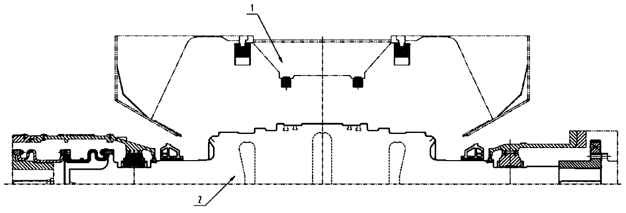
[0045] like Figure 1-6 As shown, the present disclosure provides a low pressure optical axis rotor. figure 1 It is a partial schematic diagram of the low-pressure part of the steam turbine. When the steam turbine is in the second operating state, an optical-axis rotor 2 is installed in the low-pressure cylinder 1 to replace the original bladed rotor. The compressor rotor is connected to the generator rotor and is responsible for transmitting the rotational torque.

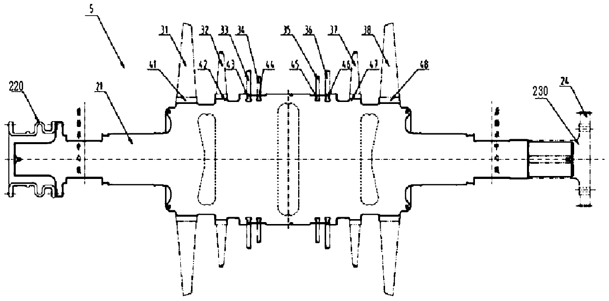
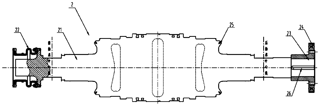
[0046] like figure 2 As shown, the optical axis rotor 2 includes a main shaft 21, a first coupling 22 mounted on the main shaft 21 and a second coupling 23 sleeved on the main shaft; For the interchangeability of some rotors with blades, remove the first coupling 220 of the original rotor 5 on the main shaft 21 , use a lathe to remove the second coupling 230 of the original rotor 5 and remove the turning gear 24 on the original rotor 5 ; With the help of the coupling bolt, the new first coupling 22 is firmly i...

Embodiment 2

[0056] This embodiment provides a steam turbine. The steam turbine has a first operating state in which all steam is used for power generation and a second operating state in which all steam is used for heating. In the first operating state, the low-pressure cylinder A low-pressure rotor with blades is installed, and in the second operating state, a low-pressure optical shaft rotor modified and processed from a low-pressure rotor with blades of the same type is installed in the low-pressure cylinder, characterized in that the optical shaft rotor is The low-voltage optical axis rotor described in Embodiment 1 of the present disclosure, such as Figure 1-6 shown.

Embodiment 3

[0058] The present embodiment: a low-voltage optical axis reforming method is provided, characterized in that the steps are as follows:

[0059] The low-pressure optical shaft rotor for No. 3 unit described in this embodiment is remanufactured from the low-pressure rotor of No. 4 unit decommissioned in Datang Huangdao Power Plant. The flow through transformation was carried out, the rotor, diaphragm, #4 and #5 bearings were replaced by ALSTOM, the jacking oil system was installed, the Baumann stage was cancelled, the deflector and reinforcing ribs of the exhaust cylinder were replaced, and the installation For the low-load water spray device, the last-stage blades of the low-pressure rotor are lengthened from 765mm to 916mm, and the number of low-pressure rotor stages remains unchanged at 2×4. The low-pressure rotor is in the form of a forged welded drum rotor, the low-pressure rotor material is 23CrNiMo747, the low-pressure rotor material brittle transition temperature is -50...


PUM


Abstract

The invention provides a low-voltage optical axis rotor, a steam turbine and a low-voltage optical axis rotor restructuring method. The low-voltage optical axis rotor comprises a main shaft, a first coupling and a second coupling, wherein the first coupling is detachably and fixedly installed on one end of the main shaft, the second coupling is detachably and fixedly installed on the other end ofthe main shaft; the main shaft is processed by removing a blade of the main shaft with the same type and a blade low-voltage rotor; the surface of the main shaft is stepped, and the optical axis rotorhas the same stiffness, deflection, shaft diameter and length as the same type of the blade low-voltage rotor; after replacing the original blade rotor with the modified optical axis rotor, other supporting structures of the steam turbine do not require additional adjustment and calibration, so the production cost of the new optical axis rotor is greatly reduced, the construction period is shortened, and the downtime loss caused by the replacement operation of a power plant is reduced.

Description

technical field [0001] The present disclosure relates to the technical field of steam turbines, in particular to a low-pressure optical shaft rotor, a steam turbine and a method for reforming a low-pressure optical shaft rotor. Background technique [0002] The statements in this section merely provide background related to the present disclosure and do not necessarily constitute prior art. [0003] Steam turbine is one of the key power equipments in the construction of thermal power plants. It is an energy conversion device that converts thermal energy into mechanical energy and then into electrical energy. The high-temperature and high-pressure steam generated by the boiler enters the steam turbine through the high-pressure steam inlet pipe, and expands step by step through each blade stage to perform work. [0004] With the increasingly severe environmental problems in our country, the adjustment of power generation installed capacity, especially the average coal consump...

Claims


Application Information

Patent Timeline
Patent Type & Authority Applications(China)
IPC IPC(8): F01K17/02F01D1/34
CPCF01D1/34F01K17/02
Inventor 祁成陆源王万军戚鹏谢富友赵乾崔文利仲崇强
Owner DATANG HUANGDAO POWER GENERATION
Why Eureka
Try Eureka