Steam and power dual-power-drive fan structure
A technology of dual power drive and electric motor, which is applied in the direction of electric components, machines/engines, liquid fuel engines, etc., can solve problems affecting normal production, complex fan drive structure, and failure to meet normal operation requirements, etc., to improve operating efficiency and stability High performance, simple structure, and low requirements on the medium
- Summary
- Abstract
- Description
- Claims
- Application Information
AI Technical Summary
Problems solved by technology
Method used
Image

Examples
Embodiment
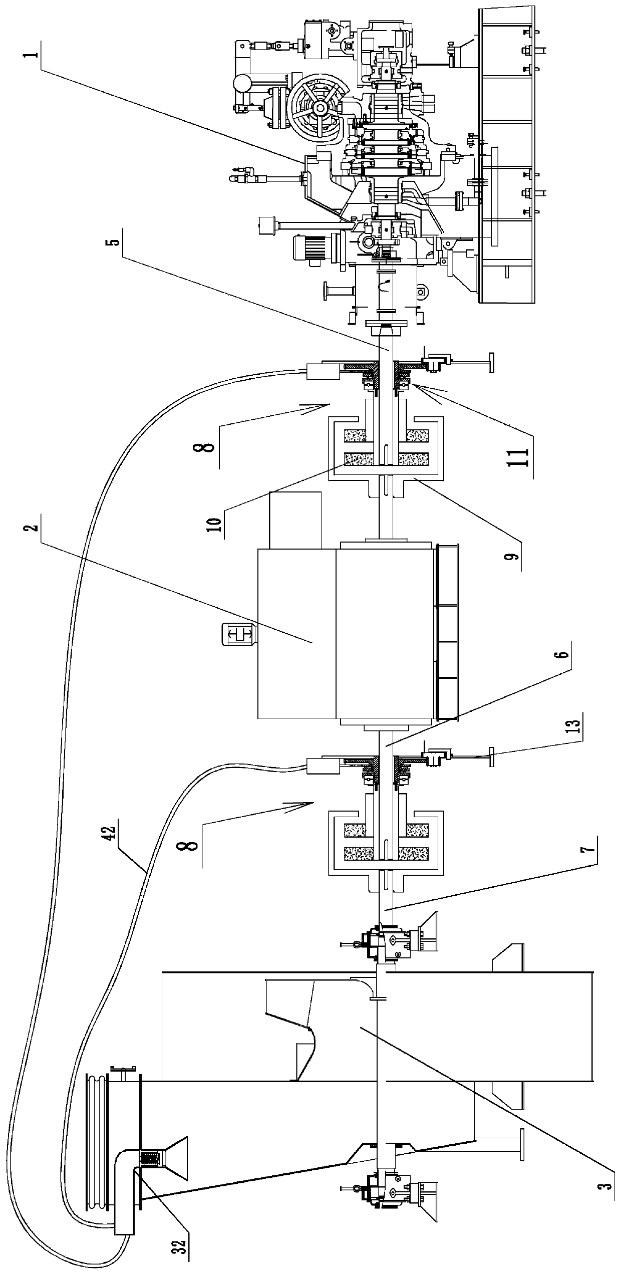
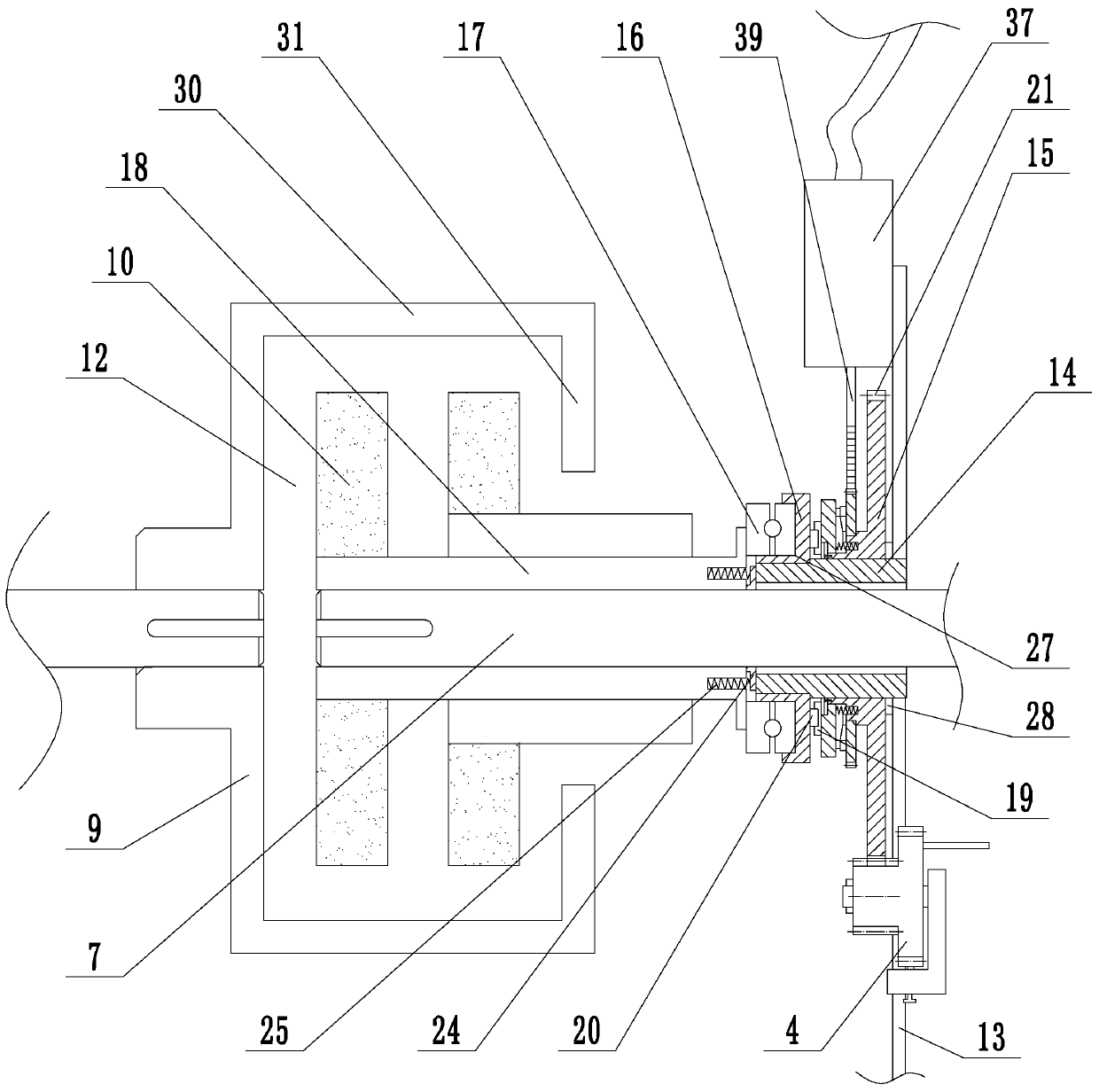
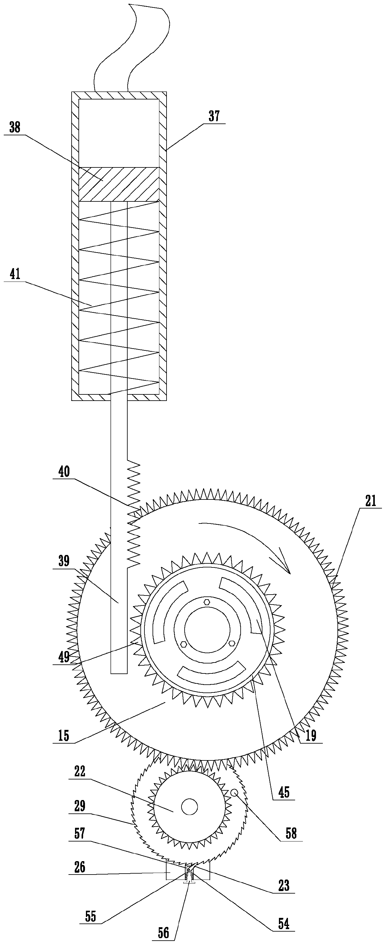
[0023] Embodiment: A steam-electric dual power drive fan structure (see attached figure 1 To attach Figure 5 ), including steam turbine 1, motor 2, fan 3, the motor is installed between the steam turbine and the fan, the steam turbine output shaft 5 is installed on the steam turbine, the motor output shaft 6 is installed on the motor, the fan shaft 7 is installed on the fan, and the blades are installed on the fan shaft. The blades are installed in the fan, and the two ends of the motor output shaft protrude from the left and right sides of the fan respectively, and permanent magnet couplings 8 are installed between the output shaft of the steam turbine and the motor output shaft and between the output shaft of the motor and the fan shaft; The coupling includes a conductor disk 9, a permanent disk 10, and an air gap adjustment mechanism 11. The conductor disk and the permanent disk are arranged opposite to each other. An air gap 12 is provided between the conductor disk and t...
PUM
 Abstract
Description
Claims
Application Information
 - R&D
- Intellectual Property
- Life Sciences
- Materials
- Tech Scout
- Unparalleled Data Quality
- Higher Quality Content
- 60% Fewer Hallucinations
Browse by: Latest US Patents, China's latest patents, Technical Efficacy Thesaurus, Application Domain, Technology Topic, Popular Technical Reports.
© 2025 PatSnap. All rights reserved.Legal|Privacy policy|Modern Slavery Act Transparency Statement|Sitemap|About US| Contact US: help@patsnap.com