Preparation method for proton exchange membrane fuel cell gas diffusion layer under high current density

A proton exchange membrane, high current density technology, used in fuel cells, electrical components, battery electrodes, etc., can solve problems such as poor thickness and uniformity, complicated preparation process of microporous layer, and unsatisfactory water management capability of gas fuel cells. , to achieve the effect of uniform thickness, improved single cell performance and low cost

Pending Publication Date: 2019-08-20
WUHAN UNIV OF TECH
View PDF12 Cites 23 Cited by
  • Summary
  • Abstract
  • Description
  • Claims
  • Application Information

AI Technical Summary

Problems solved by technology

In addition, the microporous layer in CN106299398A is two layers, and two processes of screen printing and spraying are used respectively (CN107681164A uses spraying), which makes the preparation process of the microporous layer more complicated and relatively thick and uniform. Difference
In short, the water management ability and gas fuel cell performance of the gas diffusion layer made by these existing technologies are still not ideal under high current density.

Method used


Image

  • Preparation method for proton exchange membrane fuel cell gas diffusion layer under high current density
  • Preparation method for proton exchange membrane fuel cell gas diffusion layer under high current density
  • Preparation method for proton exchange membrane fuel cell gas diffusion layer under high current density

Examples


Embodiment 1

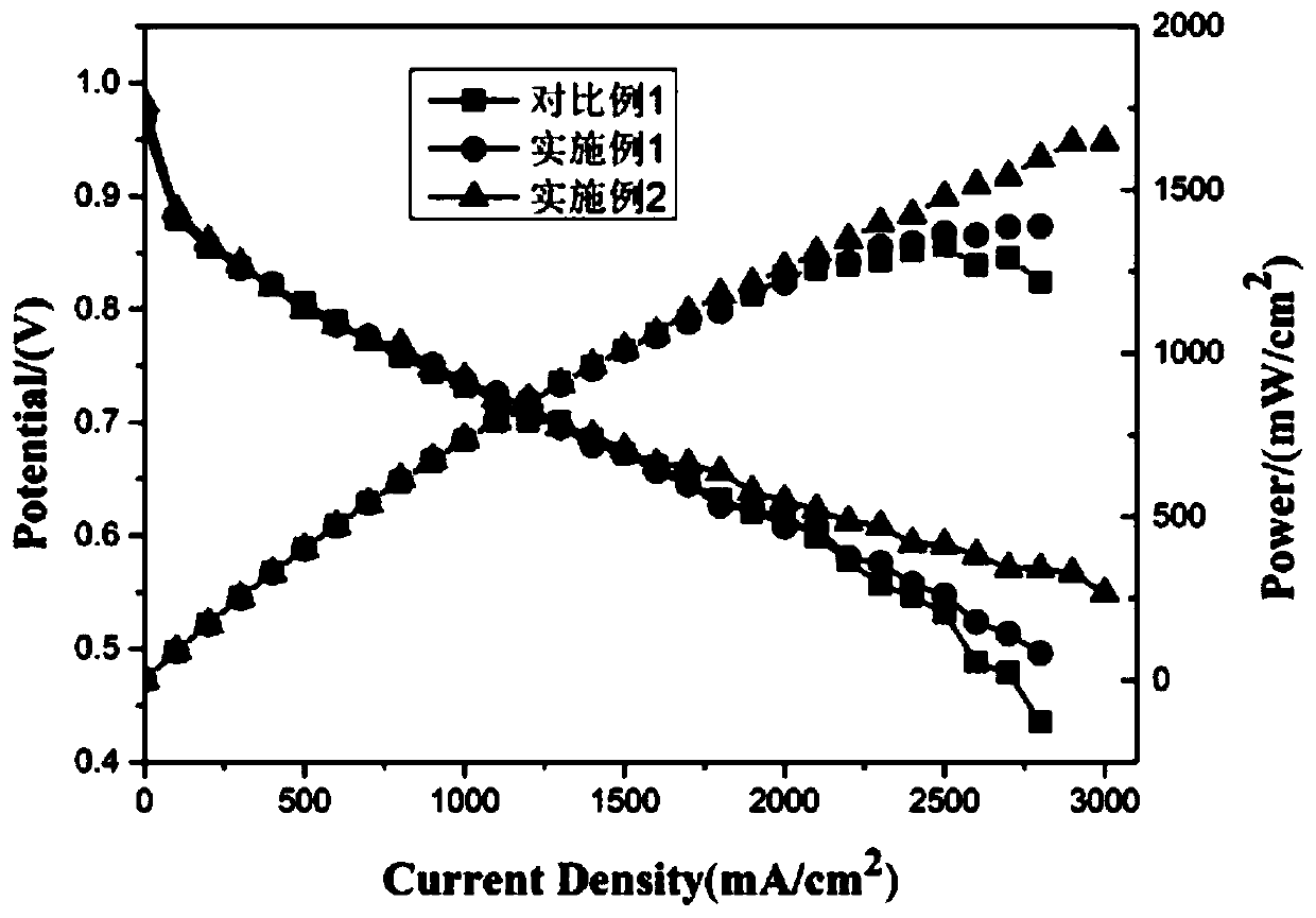
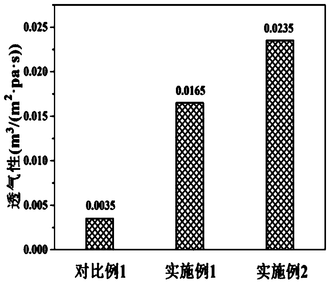
[0025] Mix 1.5g of carbon powder (Vulcan XC-72) and 15g of deionized water and stir evenly, then add 0.6g of 60% polytetrafluoroethylene (PTFE) emulsion and 0.225g of ammonium carbonate in sequence to obtain a slurry . The slurry is coated on the side of the base layer that has been hydrophobicized and dried in advance by a knife coating method to obtain a gas diffusion layer (loading 2.0mg / cm 2 ). Place the gas diffusion layer in an oven at 150°C for drying, and then transfer to a N-pass 2 Sintered in a tube furnace at 350°C for 30 minutes to obtain a gas diffusion layer with cracks. The gas diffusion layer was assembled into a fuel cell and tested in the same way as in Comparative Example 1.

Embodiment 2

[0027] Mix 1.5g of carbon powder (Vulcan XC-72) and 15g of deionized water and stir uniformly, then add 0.6g of 60% polytetrafluoroethylene (PTFE) emulsion and 0.375g of ammonium carbonate in sequence, and mix evenly to obtain a slurry . The slurry is coated on the side of the base layer that has been hydrophobicized and dried in advance by a knife coating method to obtain a gas diffusion layer (loading 2.0mg / cm 2 ). Place the gas diffusion layer in an oven at 150°C for drying, and then transfer to a N-pass 2 Sintered in a tube furnace at 350°C for 30 minutes to obtain a gas diffusion layer with larger cracks. The gas diffusion layer was assembled into a fuel cell and tested in the same way as in Comparative Example 1.

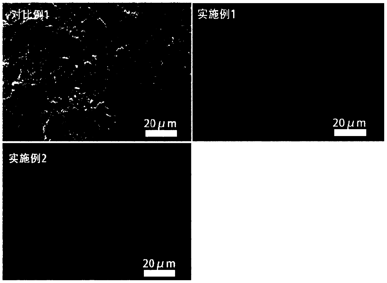
[0028] figure 1 SEM images of the gas diffusion layer microporous layer obtained in Example 1-2 and Comparative Example 1. It can be seen from the figure that there are no obvious cracks on the surface of the microporous layer in Comparative Example 1, while th...


PUM

PropertyMeasurementUnit
thicknessaaaaaaaaaa
diameteraaaaaaaaaa
quality scoreaaaaaaaaaa

Abstract

The invention relates to a preparation method for a proton exchange membrane fuel cell gas diffusion layer under high current density. The preparation method comprises the following steps: firstly, carrying out hydrophobic and drying treatment on a substrate layer, then preparing slurry by utilizing carbon powder, a solvent, a hydrophobic agent and a pore-forming agent, then uniformly attaching the slurry to the substrate layer by adopting a blade coating method and reaching a certain loading capacity, and finally drying and sintering to obtain the gas diffusion layer. A plurality of cracks are formed on the surface of the microporous layer of the gas diffusion layer after the gas diffusion layer is treated, permeation of gas and water can be effectively ensured, the water management capability of the gas diffusion layer is improved, the concentration polarization of the membrane electrode under high current density is reduced, and the performance of the proton exchange membrane fuel cell is improved. The method has the advantages of low cost, simple preparation process and the like, and is particularly suitable for commercial large-scale use.

Description

Technical field [0001] The invention relates to the technical field of fuel cells, in particular to a method for preparing a gas diffusion layer of a proton exchange membrane fuel cell facing high current density. Background technique [0002] Proton exchange membrane fuel cell (PEMFC) is a power generation device that can directly convert chemical energy in fuel (hydrogen) and oxidizer (oxygen) into electrical energy. It is environmentally friendly, free from Carnot cycle restrictions, and has high power generation efficiency. advantage. The proton exchange membrane fuel cell includes a membrane electrode, a flow field plate, a current collector, etc. The membrane electrode includes a gas diffusion layer, a catalytic layer and a proton exchange membrane. The function of the gas diffusion layer is to support the catalytic layer, collect current, conduct electrons and conduct heat, and provide transmission channels for reaction gas and product water. [0003] The traditional gas d...

Claims


Application Information

Patent Timeline
Patent Type & Authority Applications(China)
IPC IPC(8): H01M4/88H01M8/0234H01M8/0245
CPCH01M4/8807H01M8/0234H01M8/0245Y02E60/50
Inventor 李赏郭志官树猛潘牧
Owner WUHAN UNIV OF TECH
Why Eureka
Try Eureka