Eureka AIR delivers breakthrough ideas for toughest innovation challenges, trusted by R&D personnel around the world.

Error measurement system and method for high-precision linear guide rail

A linear guide rail and error measurement technology, which is applied in the direction of measuring devices, instruments, optical devices, etc., can solve the problems that errors cannot be effectively decoupled, the measurement process is complicated, and the measurement stroke is limited, so as to avoid crosstalk and measurement errors, and measure High efficiency and avoid interference effect

Inactive Publication Date: 2019-08-23
HUAZHONG UNIV OF SCI & TECH
View PDF7 Cites 15 Cited by
  • Summary
  • Abstract
  • Description
  • Claims
  • Application Information

AI Technical Summary

Problems solved by technology

[0003] At present, the error measurement of the linear guideway mainly uses a commercial laser interferometer to measure each error individually, but this method requires six installation measurements, resulting in a complicated measurement process, long time-consuming, and low measurement accuracy.
However, the error measurement using the grating diffraction method can only measure three angle errors, and due to the limitations of the grating diffraction, the measurement range is limited
[0004] Therefore, the use of multiple beams for multi-degree-of-freedom measurement is the main development direction of linear guideway error measurement. CN201510067188 discloses a laser heterodyne interference straightness measurement device and method with six-degree-of-freedom detection. The device uses laser heterodyne interferometry and laser The combination of the spot detection method realizes the simultaneous detection of the six degrees of freedom of the yaw angle, pitch angle, roll angle, horizontal straightness, vertical straightness and straightness position, but the errors measured by the device cannot be effectively Decoupled so there is crosstalk between individual errors

Method used


Image

  • Error measurement system and method for high-precision linear guide rail
  • Error measurement system and method for high-precision linear guide rail
  • Error measurement system and method for high-precision linear guide rail

Examples


Embodiment Construction

[0047] In order to make the objectives, technical solutions and advantages of the present invention clearer, the present invention will be further described in detail below with reference to the accompanying drawings and embodiments. It should be understood that the specific embodiments described herein are only used to explain the present invention, but not to limit the present invention. In addition, the technical features involved in the various embodiments of the present invention described below can be combined with each other as long as they do not conflict with each other.

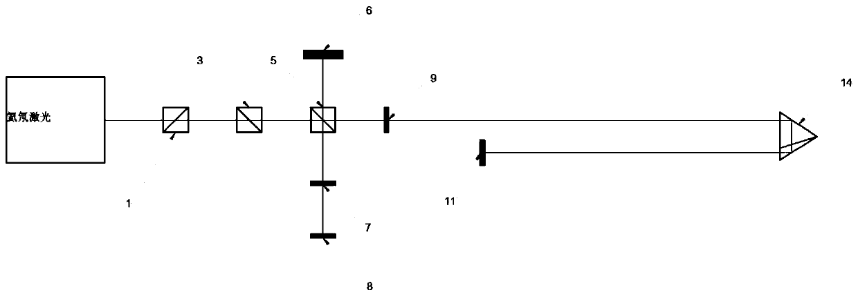
[0048] like Figures 1 to 2 As shown, the embodiment of the present invention proposes an error measurement system for a high-precision linear guide rail, the system includes a fixed unit and a moving unit, wherein:

[0049] The fixed unit is installed on the fixed plane of the CNC machine tool, and includes a helium-neon laser, 21, a second beam splitter prism 3, a polarization beam splitter prism...


PUM


Abstract

The invention belongs to the field of geometric accuracy detection, and particularly discloses an error measurement system and method for a high-precision linear guide rail. The system comprises a fixed unit and a mobile unit, wherein the fixed unit is arranged on a fixed plane of a numerical control machine tool and comprises a helium-neon laser, a first beam splitter prism, a second beam splitter prism, a polarization beam splitter prism, a first 1 / 4 wave plate and a first four-quadrant detector; and the mobile unit is arranged on a mobile workbench of the numerical control machine tool andcomprises a pyramid prism. According to the invention, the pyramid prism which is insensitive to angles is adopted to measure the straightness error, so that the crosstalk and the measurement error caused by the angle change can be effectively avoided; meanwhile, the pyramid prism is arranged on the axis or the paraxial line, so that the influence of the Abbe error on the measurement result can beeffectively reduced, and the precision of the straightness measurement is improved; and the six-degree-of-freedom synchronous measurement can be realized by arranging other devices, and each error isdecoupled and separated, so that the accuracy of the measurement result is improved.

Description

technical field [0001] The invention belongs to the field of geometric accuracy detection, and more particularly, relates to an error measurement system and method of a high-precision linear guide rail. Background technique [0002] In the field of ultra-precision machining, the accuracy of the linear guide of the CNC machine tool directly affects the motion accuracy of the CNC machine tool, and the motion accuracy of the CNC machine tool directly determines the machining accuracy. Therefore, accurate error measurement of the linear guide is an important way to ensure the machining accuracy. one. [0003] At present, the error measurement of linear guide rails mainly uses a commercial laser interferometer to measure each error individually. However, this method requires six installation measurements, resulting in complicated measurement process, long time consumption and low measurement accuracy. However, using the grating diffraction method for error measurement, only thre...

Claims


Application Information

Patent Timeline
IPC IPC(8): G01B11/27G01B11/00G01B11/26
CPCG01B11/00G01B11/26G01B11/27
Inventor 刁宽刘晓军杨文军张箎
Owner HUAZHONG UNIV OF SCI & TECH
Why Eureka
Eureka Blog
Learn More