3D printing system

A 3D printing and optical system technology, applied in the field of 3D printing systems, can solve problems such as poor mechanical properties, inability to realize mixed processing of various materials, and limited applications

Active Publication Date: 2019-08-27
ZHEJIANG UNIV
View PDF10 Cites 4 Cited by
  • Summary
  • Abstract
  • Description
  • Claims
  • Application Information

AI Technical Summary

Problems solved by technology

[0006] The disadvantages of this biological tissue molding method are: 1. Whether it is DLP or extrusion, it is impossible to use multiple materials to cooperate to complete the molding task of a biological tissue, so it is impossible to achieve mixed processing of multiple materials
The active organism is a heterogeneous mixed system containing multiple structures and various material components, and the above-mentioned method cannot complete the formation of the heterogeneous mixed system.
2. The feeding and molding speed of DLP is fast, but there is a lot of wasted material liquid, and the one-time use rate of material liquid is low
However, some of them exhibit poor mechanical properties or slow gel times, limiting their application in DLP-based 3D printing

Method used


Image

  • 3D printing system
  • 3D printing system
  • 3D printing system

Examples


Embodiment 1

[0223] Example 1: 3D printed skin for injury repair

[0224] For example Figure 10 , 11 As shown in 12 and 13, the material to be printed is first modeled, and then the model is programmed and then printed. For example, the model established as Figure 10 and 12 as shown, Figure 10 For the leather model, Figure 12 Combine the epidermis and dermis. Figure 11 It is a schematic diagram of the printing process taking 3 layers as an example. For example, the black one represents the bracket that needs to be printed, which is similar to the structure of a three-dimensional cube, and the 12 sides of the bracket use the printed bracket, and the bracket forms a hollowed-out three-dimensional structure 102, forming a unit for printing the bracket, multiple The combination of elements forms a porous structure in the form of cantilever beams. The whole unit can form a dermis support of any size, for example, the diameter can be 8 mm, the thickness of the epidermis is 1 mm, a...

Embodiment 2

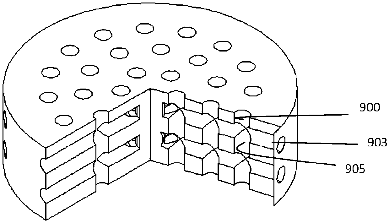
[0236] Example 2: 3D printing cartilage repair

[0237] For example figure 1 , 18 As shown, the printed material is modeled first, and then the program is controlled according to the established model, and then printed. For example, the model established as figure 1 and 18 as shown, Figure 18 It is a model of a cartilage support, which includes an upper support 901 and a lower support 902, wherein the upper support has 30 round holes 900, and the side also has 30 round holes 903, and each round hole crosses the same, for example, each of the above round holes 900 and the side The circular holes 903 are connected, for example figure 1 can be seen. The diameter of the scaffold is 4mm, the thickness of the upper layer is 1mm, and the thickness of the lower layer is 2mm. In fact, the lower layer also has corresponding 30 holes which are the same as the 30 holes in the upper layer, and next time there are no side holes.

[0238] This design is to use the scaffold for ...


PUM


Abstract

The invention provides a 3D printing system. The 3D printing system comprises an optical system, a feeding mechanism, a lifting platform and a cavity; the lifting platform and the cavity form a spacefor receiving fed materials from the feeding mechanism, the lifting platform and the feeding mechanism are independent, and the lifting platform steps relative to the optical system every time when printing is carried out; the lifting platform steps by one layer thickness every time, the lifting platform steps to realize the purpose that the optical system can focus the layer to be formed, and realize light curing; and the feeding mechanism is arranged outside the optical system, a material liquid of the feeding mechanism is outside a light curing area of the optical system, and during printing, light curing can be performed without moving the material liquid. According to the 3D printing system, multi-material alternative feeding can be realized, and a non-uniform mixing system is realized.

Description

technical field [0001] The present invention relates to a 3D printing system, as well as biological materials used for printing. Background technique [0002] It is well known that there is a large clinical need for engineered tissues due to the shortage of donor tissues and organs. Although many approaches have been tried to create engineered tissues, such as electrospinning, extrusion 3D printing and textile techniques. However, they can only produce relatively simple three-dimensional structures, which cannot meet the needs of clinical applications. Therefore, there is an urgent need to fabricate complex and layered tissue constructs with high resolution for clinical use. Recently, digital light processing (DLP)-based 3D printing technology has been used to fabricate complex 3D microstructures with high printing speed, microscale resolution, thick vertical structures, and strong interlayer bonding properties. It can simulate the precise geometry of native tissue to cre...

Claims


Application Information

Patent Timeline
Patent Type & Authority Applications(China)
IPC IPC(8): B29C64/106B29C64/20B29C64/321B29C64/30B33Y10/00B33Y30/00B33Y40/00
CPCB33Y10/00B33Y30/00B33Y40/00B29C64/106B29C64/20B29C64/30B29C64/321
Inventor 欧阳宏伟洪逸周飞飞章淑芳
Owner ZHEJIANG UNIV
Why Eureka
Try Eureka