Light redirecting film useful with solar modules
A technology of light redirection and solar photovoltaics, which is applied in the directions of solar thermal energy, solar collectors, solar heating systems, etc., and can solve problems such as reflected light escape
- Summary
- Abstract
- Description
- Claims
- Application Information
AI Technical Summary
Problems solved by technology
Method used
Image
Examples
example 1
[0097] Master tools were produced by the flying shear system and method described in US Patent No. 8,443,704 (Burke et al.) and US Application Publication No. 2009 / 0038450 (Campbell et al.). Using this method, a groove with a 45-degree offset angle and a 120-degree crown angle is cut in the base tool.
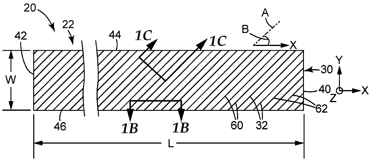
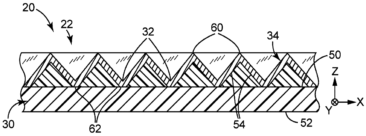
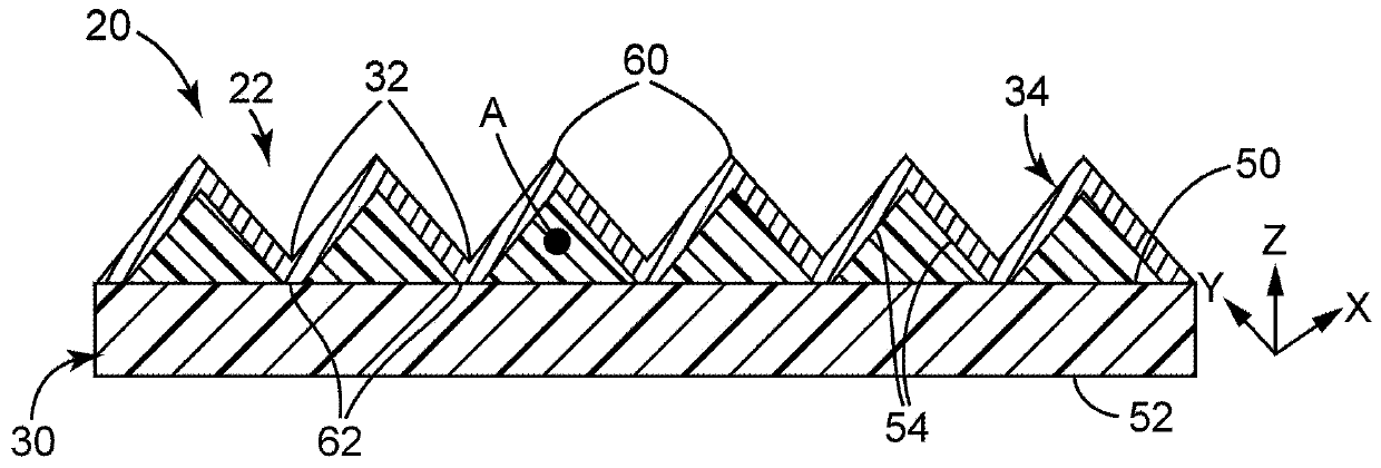
[0098] Using the base tool described in US Patent No. 6758992 (Solomon et al.), by making a polymerizable resin (e.g. , UV-curable acrylate resin) to produce microstructured films. While the base tool is in contact with the polymer film, ultraviolet radiation is used to cure the resin into the shape provided by the structure of the base tool. The off-angle of the basic tool design used to make these prisms caused the prisms to have an off-angle of 45° relative to the web axis of the PET film.
[0099] A reflective coating was applied to the microscopic prisms in a manner similar to that described in U.S. Patent No. 4,307,150 (Roche et al.). The opaque mirror metal surface is...
example 2
[0101] The base tool was created using the flying shear system and method described in Example 1. A groove with a -82° offset angle and a 120° apex angle was cut in the base tool.
[0102] Microreplicated membranes were fabricated as described in Example 1. This microreplicated film had prisms with an off-angle of -82° relative to the web direction of the film.
[0103] A reflective coating was applied to the microscopic prisms as described in Example 1. An opaque mirror-like metal surface is vapor-coated onto microscopic prisms to a thickness of approximately 80nm using high-purity (99.88+%) aluminum.
[0104] result
[0105] Light redirecting film articles were analyzed using an Eldim EZContrast L80 instrument with parallel beam reflection option (Eldim S.A., Hérouville-Saint-Clair, France). The instrument illuminates the sample with a narrow-angle source while collecting reflected light in order to analyze its angular distribution. 3M Solar Light Redirecting Film (LRF)...
example 3
[0110] Example 3: Tracking System Modeling
[0111] Where photovoltaic module 300 is part of a one-dimensional tracking photovoltaic module installation, photovoltaic module 300 will track the movement of the sun. The axis of the tracking system is usually aligned in the north-south direction, and the rotation occurs in the morning from east to afternoon in the afternoon, as shown in Figure 19. The panels are usually arranged on these trackers in a landscape orientation (such that when parallel to the ground, the long dimension of the photovoltaic modules is aligned east-west, with the Figure 19A marked as "L"). This orientation allows the collection area ratio to be arranged in an orthogonal (vertical) orientation (in Figure 19B The panels marked "P") are larger. The results of ray tracing modeling for various declination angles presented in Table 2 indicate that the 50° polarizing light redirecting film article provides the highest annual energy improvement for 30° nort...
PUM
 Abstract
Description
Claims
Application Information
 - Generate Ideas
- Intellectual Property
- Life Sciences
- Materials
- Tech Scout
- Unparalleled Data Quality
- Higher Quality Content
- 60% Fewer Hallucinations
Browse by: Latest US Patents, China's latest patents, Technical Efficacy Thesaurus, Application Domain, Technology Topic, Popular Technical Reports.
© 2025 PatSnap. All rights reserved.Legal|Privacy policy|Modern Slavery Act Transparency Statement|Sitemap|About US| Contact US: help@patsnap.com


