Protecting, cooling and chip collecting device used when laser cutting inner wall of cylinder and using method thereof

A laser cutting and cylinder-in-body technology, applied in laser welding equipment, welding equipment, metal processing equipment, etc., can solve the problems of human health injury, narrow cutting seam, no mechanical stress, etc., achieve easy operation, convenient cleaning, and prevent injury Effect

Active Publication Date: 2019-08-30
吴善方
View PDF11 Cites 3 Cited by
  • Summary
  • Abstract
  • Description
  • Claims
  • Application Information

AI Technical Summary

Problems solved by technology

The mechanical part of the laser cutter head has no contact with the workpiece, the laser cutting speed is fast, the incision is smooth and flat, and generally no subsequent processing is required; the cutting heat-affected zone is small, the plate deformation is small, the slit is narrow, the incision has no mechanical stress, and there is no shear burr; processing accuracy High, good repeatability, no damage to the surface of the material, NC programming, can process any plan, can cut the entire board with a large format, no need to open a mold, economical and time-saving, but when cutting the surface of the cylinder, the melted chips It will penetrate the cylinder and splash on the processed inner wall of the cylinder, causing the inner wall of the cylinder to be burned and scratched, resulting in the surface roughness and local mechanical properties of the inner wall of the cylinder not meeting the requirements, and it is difficult for the chips to sinter on the inner wall of the cylinder. Cleaning, and most of the cylinder must be processed by first machining the inner hole and then turning the outer circle, and the direct laser cutting of the solid cylinder that has not been drilled and reamed is prone to heat accumulation and internal deformation, so it cannot be reversed The processing procedure is avoided, and the chips are easy to escape into the air, which will cause harm to human health. Over time, it will easily lead to silicosis. Therefore, there is no device on the market to protect the inner wall and collect chips during laser cutting of the cylinder.

Method used


Image

  • Protecting, cooling and chip collecting device used when laser cutting inner wall of cylinder and using method thereof
  • Protecting, cooling and chip collecting device used when laser cutting inner wall of cylinder and using method thereof
  • Protecting, cooling and chip collecting device used when laser cutting inner wall of cylinder and using method thereof

Examples


Embodiment Construction

[0018] The present invention will be further explained below in conjunction with the drawings:

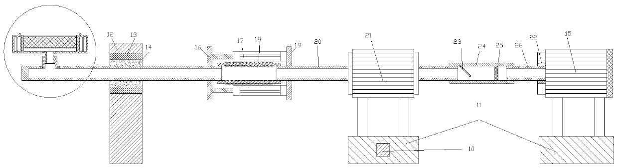
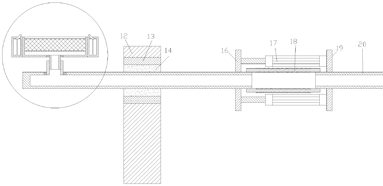
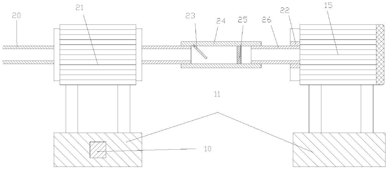
[0019] Reference attached figure 1 , 2 , 3, 4, 5, 6, 7: The laser cutting inner wall protection and cooling chip collecting device of the cylinder in this embodiment includes a splicing pipe 1, and the splicing pipe 1 is threadedly connected to the inner wall of the top left half of the splicing pipe 1 2. The bottom of the connecting pipe 2 is connected to the inside of the splicing pipe 1. A U-shaped box 9 is provided above the connecting pipe 2, and a U-shaped cavity 7 is provided in the U-shaped box 9 and the top of the U-shaped cavity 7 is provided. There is a cooling mesh 8, the top of the cooling mesh 8 communicates with the outside, the bottom of the U-shaped cavity 7 is screwed with an adjusting tube 3, the top of the adjusting tube 3 communicates with the U-shaped cavity 7, and the bottom of the adjusting tube 3 Threaded connection with the top of the connecting pipe 2, the b...


PUM


Abstract

The invention discloses a protecting, cooling and chip collecting device used when laser cutting an inner wall of a cylinder. The device comprises a first splicing pipe, wherein the inner wall of thetop of the left half part of the first splicing pipe is in threaded connection with a connecting pipe; the bottom of the connecting pipe communicates with the inside of the first splicing pipe; and aU-shaped box is arranged above the connecting pipe. The device has beneficial effects of being simple in structure and convenient to operate, and successfully solving a series of problems that scratch, burn, sinter and the like to the inner wall of the cylinder are caused by molten chips sprayed when the outside of the cylinder is cut by a laser; a laser cutting head can be symmetrically tracked inside the cylinder by the U-shaped box according to a cutter path of the laser cutting head, and the molten chips are collected in the U-shaped cavity after being cooled when the spraying angle of themolten chips is small, and then conveyed by a U-shaped cavity, a first connecting pipe, a corrugated pipe and a second connecting pipe into a chip collecting pipe to be temporarily stored, so that itis convenient for people to clean, and meanwhile, the damage to people caused by chip splashing is prevented.

Description

Technical field [0001] The invention relates to the technical field of laser cutting, in particular to a device for protecting, cooling, and collecting chips for laser cutting the inner wall of a cylinder and a method of use. Background technique [0002] At present, the laser cutting machine focuses the laser light emitted from the laser into a high power density laser beam through the optical path system. The laser beam irradiates the surface of the workpiece to make the workpiece reach the melting point or boiling point. The laser cutting process uses an invisible beam to replace the traditional mechanical knife. It has high precision and fast cutting. It is not limited to the limitation of cutting patterns. Automatic layout saves materials and cuts. The characteristics of smoothness and low processing cost will gradually improve or replace the traditional metal cutting process equipment. The mechanical part of the laser cutter head has no contact with the workpiece, the lase...

Claims


Application Information

Patent Timeline
Patent Type & Authority Applications(China)
IPC IPC(8): B23K26/70B23K26/38
CPCB23K26/38B23K26/702B23K26/703
Inventor 吴善方
Owner 吴善方
Why Eureka
Try Eureka