Online frequency measurement system for quartz wafer polishing and grinding

A quartz wafer, frequency measurement technology, applied in the direction of frequency measurement device, frequency to amplitude conversion, etc., can solve the problems of inability to measure, limited amplification ability, limited noise removal ability, etc., to achieve convenient processing and acquisition, improved measurement accuracy, and good The effect of site adaptability

Pending Publication Date: 2019-08-30
RES INST OF ZHEJIANG UNIV TAIZHOU
View PDF0 Cites 3 Cited by
  • Summary
  • Abstract
  • Description
  • Claims
  • Application Information

AI Technical Summary

Problems solved by technology

Its main disadvantages are: it cannot be measured at low frequencies below 5M, and it cannot be measured on polished wafers.
The main reasons are as follows: (1) The original circuit is limited by the hardware and has limited amplification ability and limited noise removal ability, which is not enough to distinguish and analyze the signals entering the low frequency and polishing
(2) Low-frequency and polishing signals are inherently small. Even if the original system can amplify enough, but because the existing DC component will also be amplified at the same time, it cannot be sampled if it exceeds the ADC voltage range of the single-chip microcomputer.
[0003] At the same time, in the prior art, the online frequency monitor (Auto Lapping Controlsystem-ALC) of TRANSAT Company of the United States conducts online measurement and control of the wafer frequency during the grinding process, and there is a problem of "jumping of frequency measurement values ​​in certain frequency bands", and ALC cannot be measured on polished quartz wafers, which cannot meet the current production environment

Method used


Image

  • Online frequency measurement system for quartz wafer polishing and grinding
  • Online frequency measurement system for quartz wafer polishing and grinding
  • Online frequency measurement system for quartz wafer polishing and grinding

Examples


Embodiment Construction

[0030] The following will clearly and completely describe the technical solutions in the embodiments of the present invention with reference to the accompanying drawings in the embodiments of the present invention. Obviously, the described embodiments are some of the embodiments of the present invention, but not all of them. Based on the embodiments of the present invention, all other embodiments obtained by persons of ordinary skill in the art without making creative efforts belong to the protection scope of the present invention.

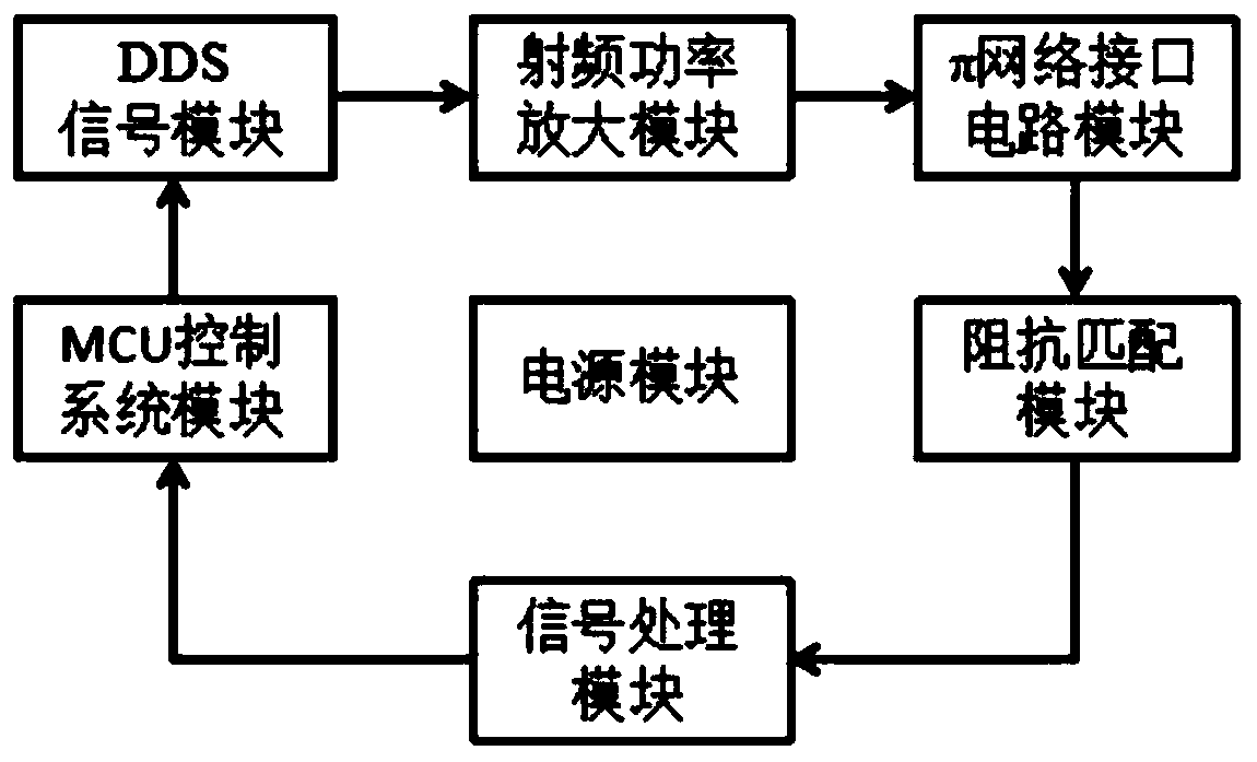
[0031] refer to figure 1, is shown as a structural block diagram of an online frequency measurement system for quartz wafer polishing and grinding according to an embodiment of the present invention, including a DDS signal module, a radio frequency power amplifier module, a π network interface circuit module, an impedance matching module, a signal processing module, an MCU control system module and The power supply module used to provide the worki...


PUM


Abstract

The invention discloses an online frequency measurement system for quartz wafer polishing and grinding, comprising a DDS signal module, a radio frequency power amplification module, a phi network interface circuit module, an impedance matching module, a signal processing module, an MCU control system module and a power module for providing a working voltage for the above modules, wherein the DDS signal module generates a specified frequency range and a sweep frequency velocity according to a specified sweep frequency instruction issued by the MCU control system module, and outputs a sinusoidalsweep frequency signal of the power, power amplification is performed on a resonant signal generated by the DDS signal module via the radio frequency power amplification module, the signal subject tothe power amplification is connected to the phi network interface circuit module, the sinusoidal sweep frequency signal acts on a wafer through a phi network to cause the same to generate mechanicalvibration, meanwhile the mechanical vibration of the wafer generates an alternating electric field, when the external positive sweep frequency signal frequency is a certain particular value, the amplitude is significantly increased, and when a signal with a significantly increased amplitude is generated, an effective signal is captured.

Description

technical field [0001] The invention belongs to the technical field of quartz wafer detection, in particular to an on-line frequency measurement system for quartz wafer polishing. Background technique [0002] In the prior art, the on-line frequency measurement of the quartz chip is mostly through signal acquisition and amplification, then peak detection, amplification and filtering, and DC coupling into the single-chip ADC for DC sampling. Its main disadvantages are: it cannot be measured at low frequencies below 5M, and it cannot be measured on polished wafers. The main reasons are as follows: (1) The original circuit is limited by the hardware and has limited amplification ability and limited noise removal ability, which is not enough to distinguish and analyze the signals entering the low frequency and polishing. (2) Low frequency and polishing signals are inherently small, even if the original system can amplify enough, but because the existing DC component will also b...

Claims


Application Information

Patent Timeline
Patent Type & Authority Applications(China)
IPC IPC(8): G01R23/06
CPCG01R23/06
Inventor 郭彬陈一信潘凌锋陈浙泊颜文俊林斌
Owner RES INST OF ZHEJIANG UNIV TAIZHOU
Why Eureka
Try Eureka