
A kind of array substrate and its manufacturing method and display panel

A technology of array substrates and substrate substrates, which is applied in semiconductor/solid-state device manufacturing, semiconductor devices, electrical components, etc., and can solve problems such as thinner thickness, short circuit of data lines, poor coverage, etc.

Active Publication Date: 2021-09-10
BOE TECH GRP CO LTD +1
View PDF2 Cites 0 Cited by
  • Summary
  • Abstract
  • Description
  • Claims
  • Application Information

AI Technical Summary

Problems solved by technology

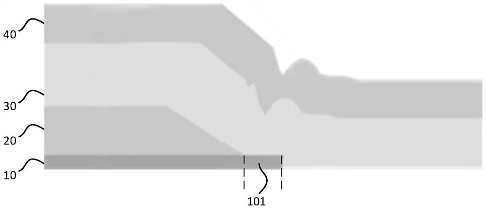
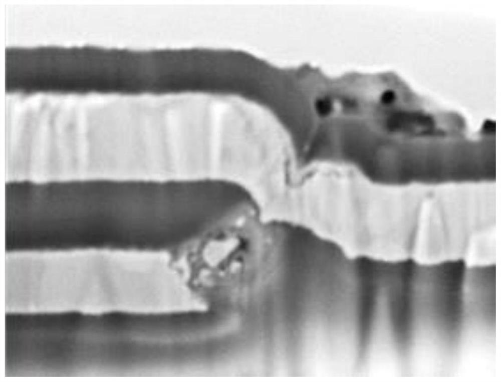
[0004] Due to the GI Tail, wrinkles appear at the intersection of the interlayer insulating layer (Inter Layer Dielectrics, ILD) 30 and the Gate metal 20 in the metal wiring area. After the source-drain (SD) 40 overlaps, the wrinkles cause The thickness of the ILD30 between the Gate metal wiring 20 and the SD metal wiring 40 becomes thinner due to poor coverage, and at the same time, a similar tip phenomenon will be formed after the SD metal 40 is deposited, such as figure 2 As shown, the short circuit of the data line (Data Gate Short, DGS) is prone to occur.

Method used


Image

  • A kind of array substrate and its manufacturing method and display panel
  • A kind of array substrate and its manufacturing method and display panel
  • A kind of array substrate and its manufacturing method and display panel

Examples


Embodiment Construction

[0043] In order to make the purpose, technical solutions and advantages of the present application clearer, the technical solutions in the embodiments of the present application will be clearly and completely described below in conjunction with the drawings in the embodiments of the present application.

[0044] At present, there is no GI Tail in the metal traces of the array substrate, which leads to wrinkles at the intersection of the ILD and the Gate metal traces. After the SD metal traces are overlapped, the folds lead to gaps between the Gate metal traces and the SD metal traces. The thickness of the ILD film layer becomes thinner due to poor covering ability, and at the same time, a similar tip phenomenon will be formed after SD metal deposition, which is prone to DGS failure.

[0045] In view of this, the difference between the length of the gate insulating layer and the length of the gate in the metal wiring area of ​​the array substrate in the embodiment of the present...


PUM


Abstract

The present application discloses an array substrate, a manufacturing method thereof, and a display panel, which are used to reduce the probability of DGS occurring in a display device and improve the yield rate of the array substrate. The array substrate includes: a base substrate, an active layer covering the base substrate, a gate insulating layer covering the active layer, a gate covering the gate insulating layer, and a source-drain metal layer covering the gate; wherein, the array substrate includes a control area and a metal wiring area, which are located in the metal wiring area along the channel extension direction of the active layer The difference between the length of the gate insulating layer and the length of the gate is a first length difference, and the difference between the length of the gate insulating layer located in the control region and the length of the gate is A second length difference, the first length difference is smaller than the second length difference.

Description

technical field [0001] The present application relates to the technical field of semiconductors, in particular to an array substrate, a manufacturing method thereof, and a display panel. Background technique [0002] A thin film transistor (Thin Film Transistor, TFT) is mainly used to drive sub-pixels of a liquid crystal display (Liquid Crystal Display, LCD) and an organic light-emitting diode (Organic Light-Emitting Diode, OLED) display. The driving backplane made of TFT array is a key component for the display to achieve higher pixel density, aperture ratio and improved brightness. [0003] Usually, the driving backplane channel of the top emission structure is short, and the characteristics of the TFT are easily affected by the short channel effect. In order to reduce the influence of the short channel effect, it is necessary to ensure that the gate insulating layer (Gate Insulator, the length of GI) 10 is longer than the length of gate (Gate) 20, as figure 1 shown. Wh...

Claims


Application Information

Patent Timeline
Patent Type & Authority Patents(China)
IPC IPC(8): H01L27/12H01L21/77
CPCH01L27/1237H01L27/124H01L27/1259H01L27/1244H01L27/1288
Inventor 宋威赵策丁远奎王明刘宁胡迎宾彭俊林倪柳松
Owner BOE TECH GRP CO LTD
Learn More