Tunable antenna and mobile communication electronic device

A technology for tuning antennas and electronic equipment, which is applied in the field of 5G mobile communications, can solve the problems of limited neutralization effect of multi-band antennas, reduce the mutual coupling of antennas and hold them at the same time, and achieve the effect of providing voltage division, improving the isolation between antennas, The effect of widening the antenna bandwidth

Inactive Publication Date: 2019-09-03
TIANTONG RUIHONG TECH CO LTD
View PDF7 Cites 5 Cited by
  • Summary
  • Abstract
  • Description
  • Claims
  • Application Information

AI Technical Summary

Problems solved by technology

However, the length of the neutralization line (neutralization line) is fixed, which determines that it is only effective for fixed frequencies, and the neutralization effect for multi-band antennas is limited.
And obviously when more antennas coexist, it is impossible to connect all antennas with a neutral line
However, in the existing technology, when multiple antennas are placed together, the ground current reversely superimposes to reduce mutual coupling, which cannot solve the deterioration problem that the antennas are held simultaneously within a small area.

Method used


Image

  • Tunable antenna and mobile communication electronic device
  • Tunable antenna and mobile communication electronic device
  • Tunable antenna and mobile communication electronic device

Examples


Embodiment 1

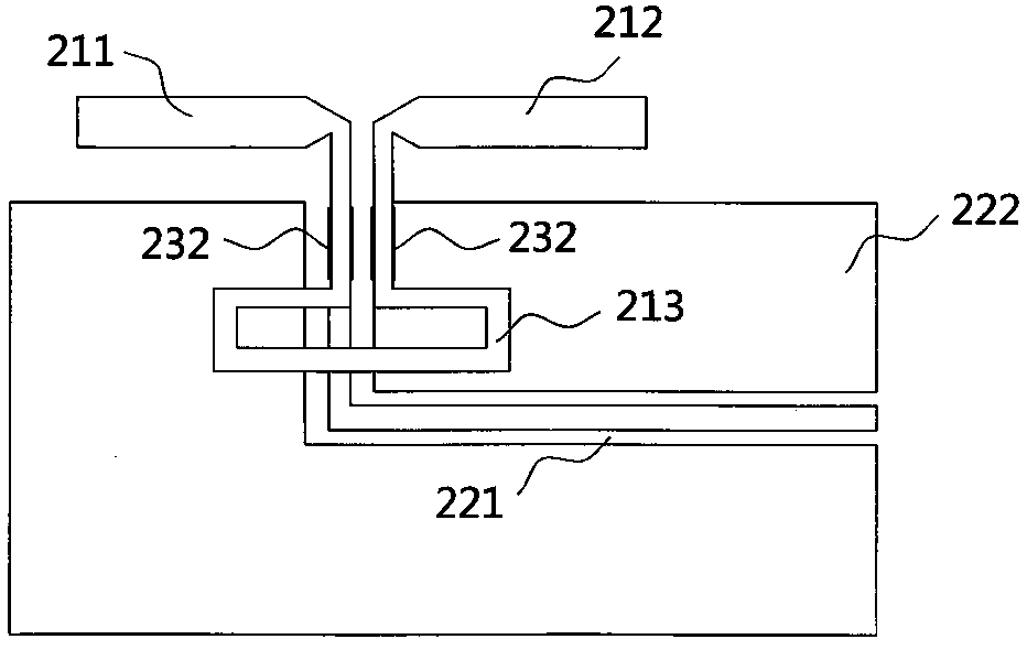
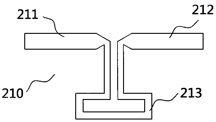
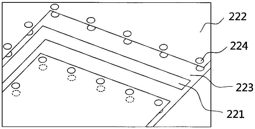
[0023] Embodiment 1: in combination with Figure 1~6 As shown, a tunable antenna includes a broadband tunable MIMO multi-antenna 20, and the broadband tunable MIMO multi-antenna 20 is composed of eight similar dipole antennas 210-280 , and are evenly and symmetrically distributed on both sides of the electronic device 10, with four placed on each side, which can effectively prevent the user from absorbing the antenna signal of the mobile terminal electronic device 10 in various possible use states. That is, when the user holds the mobile terminal electronic device 10 with the left hand, the right hand, or both hands with the horizontal screen, they will not hold all the antennas at the same time, which will become a "death grip" and cause the signal to deteriorate sharply or even drop the line. At the same time, the substantially uniform distribution makes the distance between the dipole antennas 210-280 not too close, effectively avoiding mutual coupling between adjacent ante...

Embodiment 2

[0027] Embodiment 2: as Figure 7 As shown, a mobile communication electronic device has a first long side 110 and a second long side 120, and the broadband tunable MIMO multiple antennas 20 are evenly and symmetrically distributed on the first long side 110 and the second long side 110 and the second long side 120. The second long side is 120. The broadband tunable MIMO multi-antenna 20 includes a dipole antenna 210, a dipole antenna 220, a dipole antenna 230, a dipole antenna 240, a dipole antenna 250, and a dipole antenna 260 , a dipole antenna 270 , and a dipole antenna 280 .


PUM


Abstract

The invention discloses a tunable antenna. The tunable antenna comprises a broadband tunable multiple-input multiple-output (MIMO) multiple antenna which is formed by an even number of antenna units which are uniformly and symmetrically distributed at two sides of an electronic device, a first radiation arm and a second radiation arm are respectively connected with the two ends of a Balun, and theradiation arm and the second radiation arm are respectively conducted with an antenna feeder and a metal ground through a first antenna elastic sheet and a second antenna elastic sheet; a tunable device is arranged at the input impedance matching position of a dipole antenna and comprises a multi-channel switch SW, a variable capacitor C1 and a fixed inductor L1 which are connected in series andpositioned in a main channel, and the variable capacitor C1 is connected between the first radiation arm and / or the second radiation arm of the dipole antenna and the metal ground in parallel. The tunable antenna effectively weakens the antenna pattern distortion caused by the ground current flowing along the edge of the metal ground, effectively avoids the attenuation of the antenna performance of the mobile communication electronic equipment caused by hand holding in various states.

Description

technical field [0001] The invention relates to the field of 5G mobile communication, in particular to a tunable antenna and mobile communication electronic equipment. Background technique [0002] At present, the pre-commercial work of 5G (fifth-generation mobile communication) has been launched in various countries, and the Ministry of Industry and Information Technology also stated that my country will realize 5G commercial use in 2020. 5G (fifth generation mobile communication) communication frequency bands include Sub 6GHz and millimeter wave (electromagnetic waves with a wavelength of 1mm to 10mm, that is, electromagnetic waves with a frequency of 30 to 300GHz, such as 28GHz, 37 GHz, 39 GHz, 60GHz, etc.) frequency bands. Among them, Sub6GHz, such as 3.6-3.6GHz and 4.8-5.0GHz microwave frequency bands, will be commercialized faster than millimeter wave frequency bands. [0003] Multiple-input multiple-output (MIMO) multi-antenna system is one of the main technologies o...

Claims


Application Information

Patent Timeline
Patent Type & Authority Applications(China)
IPC IPC(8): H01Q1/38H01Q1/48H01Q1/50H01Q21/06H04M1/02
CPCH01Q1/38H01Q1/48H01Q1/50H01Q21/061H04M1/026
Inventor 朱德进
Owner TIANTONG RUIHONG TECH CO LTD
Why Eureka
Try Eureka