Scanning type laser shock peening device

A laser shock strengthening and scanning technology, which is applied in the field of metal surface treatment, can solve the problems of low efficiency of laser shock strengthening, achieve the effect of facilitating laser shock strengthening processing, facilitating laser shock strengthening processing, and improving matching and flexibility

Pending Publication Date: 2019-09-06
西安天瑞达光电技术股份有限公司
View PDF0 Cites 10 Cited by
  • Summary
  • Abstract
  • Description
  • Claims
  • Application Information

AI Technical Summary

Problems solved by technology

[0005] The purpose of the present invention is to at least solve the problem of low laser shock peening efficiency, and provide a scanning laser shock peening device

Method used


Image

  • Scanning type laser shock peening device
  • Scanning type laser shock peening device
  • Scanning type laser shock peening device

Examples


Embodiment 2

[0042] A scanning laser shock peening device in this embodiment has basically the same structure as that in Embodiment 1, the difference is that:

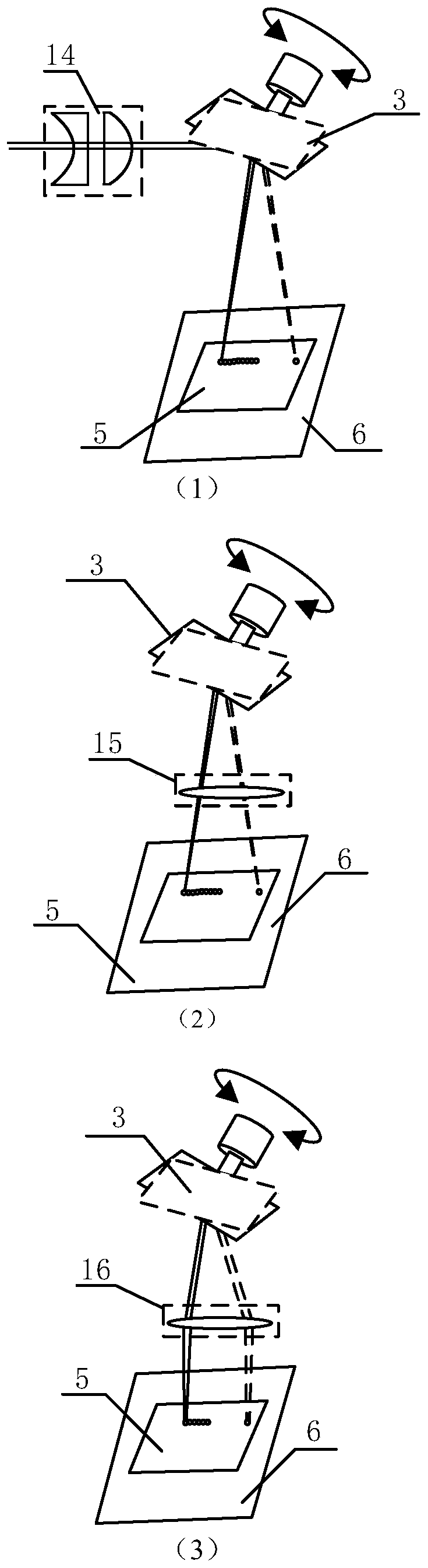
[0043] The focusing device 4 is arranged on the output (reflection) laser light path of the one-dimensional scanning galvanometer 3, such as image 3 (2) shown.

Embodiment 3

[0045] A scanning laser shock peening device in this embodiment has basically the same structure as that in Embodiment 1, the difference is that:

[0046] The focusing device 4 adopts a telecentric field mirror 16, which is arranged on the output (reflection) laser light path of the one-dimensional scanning vibrating mirror 3, such as image 3 (3) shown.

Embodiment 4

[0048] A scanning laser shock peening device in this embodiment has basically the same structure as that in Embodiment 1, the difference is that:

[0049] Laser 1 adopts a low repetition frequency and high energy laser below 50 Hz.

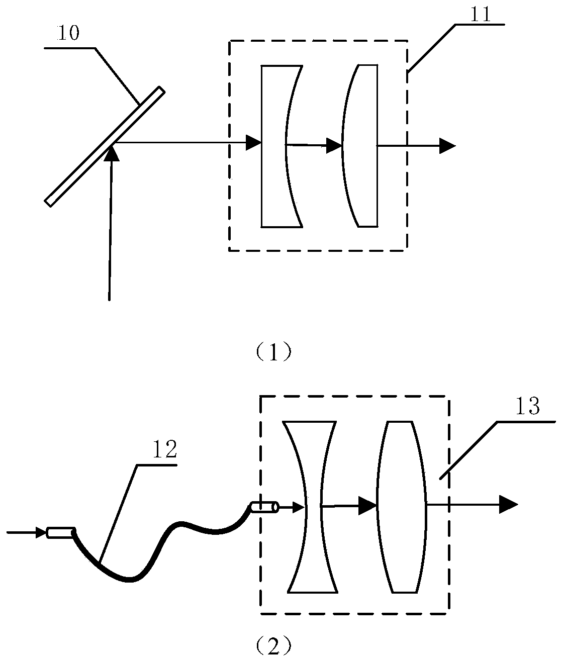
[0050] Such as figure 2 As shown in (2), the light guide device 2 adopts an optical fiber 12 or other flexible light guide device, and the optical fiber 12 cooperates with the optical fiber transmission shaping device 13 to shape and transmit the laser output from the laser 1 .

[0051] The focusing device 4 adopts an ordinary focusing mirror, which is arranged on the optical path between the one-dimensional scanning vibrating mirror 3 and the metal part 5 , and moves and deflects together with the one-dimensional scanning vibrating mirror 3 .

[0052] The water constrained layer loading device 8 is a movable structure.

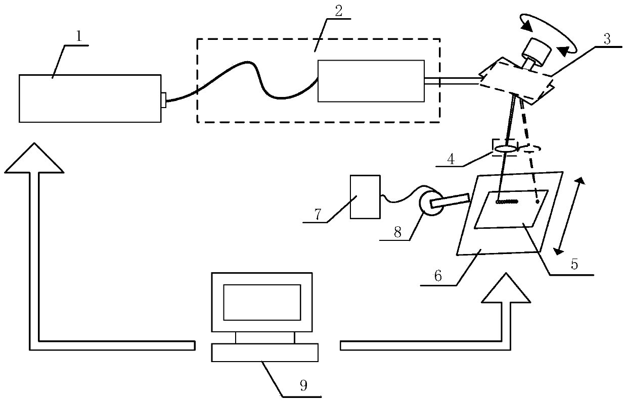
[0053] The laser 1 , light guiding device 2 , one-dimensional scanning galvanometer 3 , focusing device 4 , moving clamping ...


PUM


Abstract

The invention relates to metal surface treatment, in particular to a scanning type laser shock peening device. The scanning type laser shock peening device comprises a laser, a light guide device, a restraint layer loading device, a one-dimensional scanning galvanometer and a focusing device. The light guide device is arranged between the laser and the one-dimensional scanning galvanometer. A metal part is located on an output light path of the one-dimensional scanning galvanometer. The metal part is provided with a restraint layer and a motion clamping device. The focusing device is arrangedon a light path between the light guide device and the metal part. A high-repetition-frequency low-energy laser shock peening method is high in frequency, and the machining efficiency is greatly improved.

Description

technical field [0001] The invention belongs to the field of metal surface treatment, and in particular relates to a scanning laser shock strengthening device. Background technique [0002] Laser shock strengthening technology is a technology that uses plasma shock waves generated by strong laser beams to improve the fatigue resistance, wear resistance and corrosion resistance of metal materials. It has outstanding advantages such as non-contact, no heat-affected zone, strong controllability and remarkable strengthening effect. The function of the coating on the surface of the metal workpiece is mainly to protect the workpiece from being burned by the laser and to enhance the absorption of laser energy. Currently, commonly used coating materials include black paint and aluminum foil. In addition to restricting the expansion of the plasma to increase the peak pressure of the shock wave, the confinement layer can also prolong the action time by reflecting the shock wave. Curr...

Claims


Application Information

Patent Timeline
Patent Type & Authority Applications(China)
IPC IPC(8): C21D10/00
CPCC21D10/005
Inventor 何艳磊程江勇李国杰薛鹏波刘元伟毋乃靓何强世
Owner 西安天瑞达光电技术股份有限公司
Why Eureka
Try Eureka