
Device and process method for ERDIII cement plant ultra-low emission denitration

A cement plant and denitrification technology, which is applied in the field of flue gas denitrification, can solve the problems of high consumption of ammonia water, spraying ammonia water, and failure to achieve it, and achieve the effects of avoiding secondary pollution, reducing the burden of denitrification, and reducing the amount of use

Pending Publication Date: 2019-09-10
上海三融环保工程有限公司
View PDF1 Cites 5 Cited by
  • Summary
  • Abstract
  • Description
  • Claims
  • Application Information

AI Technical Summary

Problems solved by technology

[0004] (1) ERD + coal-fired saturated steam catalytic combustion denitrification technology still cannot meet the requirements of maintaining the NOx emission concentration within 50mg / Nm³ or stably operating at 50mg / Nm³, requiring a large amount of ammonia injection, causing secondary pollution
[0005] (2) The comprehensive denitrification efficiency of ERD+ reaches over 80%, which cannot meet lower emission requirements
[0006] (3) The consumption of ammonia water is still relatively large, and a large amount of ammonia water is sprayed in pursuit of ultra-low emissions, but it is easy to cause high ammonia escape and cause corrosion to subsequent equipment

Method used


Image

  • Device and process method for ERDIII cement plant ultra-low emission denitration
  • Device and process method for ERDIII cement plant ultra-low emission denitration
  • Device and process method for ERDIII cement plant ultra-low emission denitration

Examples


Embodiment Construction

[0062] The following will clearly and completely describe the technical solutions in the embodiments of the present invention with reference to the accompanying drawings in the embodiments of the present invention. Obviously, the described embodiments are only some, not all, embodiments of the present invention. Based on the embodiments of the present invention, all other embodiments obtained by persons of ordinary skill in the art without making creative efforts belong to the protection scope of the present invention.

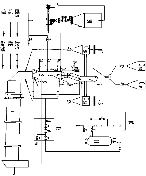
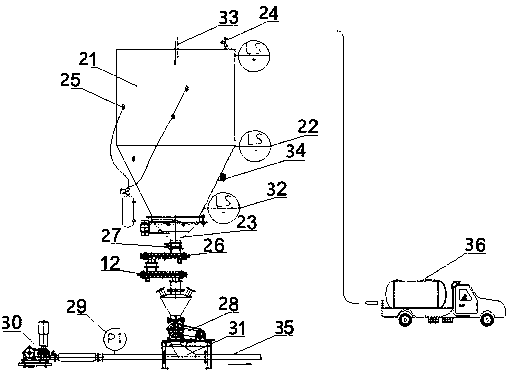
[0063] Such as figure 1 As shown, the present invention provides an ultra-low emission denitrification device for an ERDIII cement plant, which includes a calciner and a powder denitrification agent delivery device. The bottom of the calciner is provided with a secondary air inlet, which is connected to a cement rotary kiln. The calciner 16 includes a reduction zone 2 , a main combustion zone 3 , a reburning zone 4 and a burnout zone 17 from bottom to top.

...


PUM


Abstract

The invention discloses a device and a process method for ERDIII cement plant ultra-low emission denitration. The device for ERDIII cement plant ultra-low emission denitration comprises a decomposition furnace and a powder denitration agent conveying unit, wherein the bottom part of the decomposition furnace is provided with a secondary wind inlet which is connected with a cement rotary kiln; thedecomposition furnace comprises a reducing zone, a main burning zone, a reburning zone and a burnout zone from bottom to top; the reducing zone is equipped with a reducing zone saturated steam catalytic burner; the reburning zone is equipped with a reburning zone saturated steam catalytic burner; the main burning zone is connected with tertiary wind; the burnout zone is connected with burnout wind; and the discharge pipe of the powder denitration agent conveying unit is connected with a denitration agent spray gun which is connected with the reburning zone. According to the invention, throughintroduction of a denitration catalyst, the usage amount of ammonia water for denitration is reduced; the cost is saved; ammonia escape is reduced; more economy and environmental friendliness are achieved; and due to reduction of ammonia escape, corrosion to subsequent equipment is avoided.

Description

technical field [0001] The invention belongs to the field of flue gas denitrification in cement production lines, and specifically relates to an ultra-low emission denitrification device of an ERDIII cement plant; in addition, the invention also relates to an ultra-low emission denitration process method of an ERDIII cement plant. Background technique [0002] SNCR Selective Non-Catalytic Reduction Denitrification—the denitrification technology with the largest market share, the ammonia nitrogen ratio is designed to be 1~1.5. The high operating cost of denitrification increases the burden on enterprises. [0003] The utility model patent with the application number 201720210300.1 filed by the applicant on March 6, 2017 discloses an ERD+ coal-fired saturated steam catalytic combustion denitrification device. The cement rotary kiln is connected; the lower section of the calciner includes a reduction zone, a main combustion zone, and a reburning zone from bottom to top, and a ...

Claims


Application Information

Patent Timeline
IPC IPC(8): C10J3/48B01D53/86B01D53/56F23C7/00F23K3/00F23B40/00
CPCC10J3/48B01D53/8631F23C7/00F23K3/00F23B40/00B01D2257/40B01D2258/0283
Inventor 许长庆龙成苗娜曾赐福
Owner 上海三融环保工程有限公司
Learn More