

Blast furnace gas desulfurization method and system
A blast furnace gas and desulfurization system technology, which is applied in combustible gas purification, removal of gas pollutants, combustible gas purification/reconstruction, etc., can solve the problem of high desulfurization cost, and achieve the effect of reducing desulfurization cost and improving service life.
- Summary
- Abstract
- Description
- Claims
- Application Information
AI Technical Summary
Problems solved by technology
Method used
Image

Examples
Embodiment 1
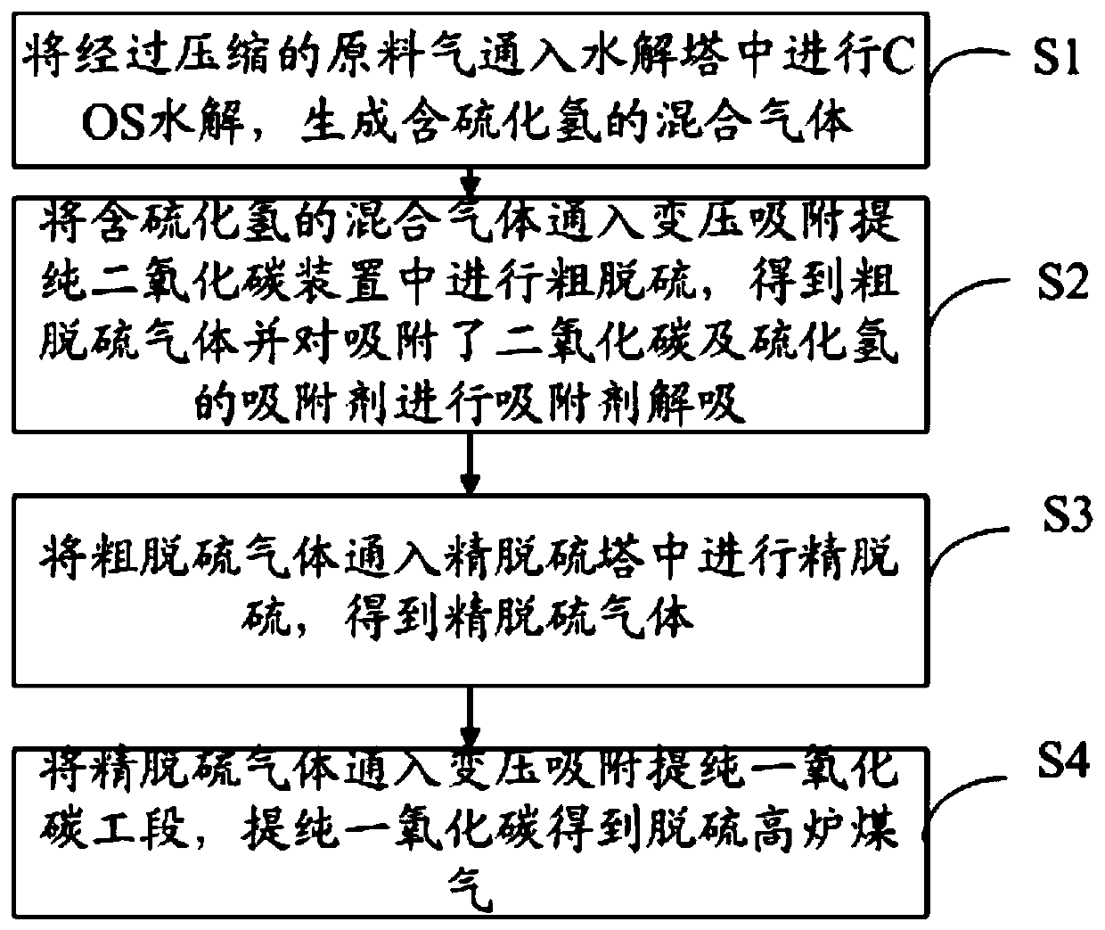
[0040] See figure 1 , figure 1 It is a schematic flow diagram of a blast furnace gas desulfurization method according to an embodiment of the present invention, as figure 1 As shown, the method includes the following steps:
[0041] S1. Pass the compressed feed gas into the hydrolysis tower for COS hydrolysis to generate a mixed gas containing hydrogen sulfide;
[0042] S2. Pass the mixed gas containing hydrogen sulfide into the carbon dioxide purification device by pressure swing adsorption for rough desulfurization, obtain crude desulfurized gas, and perform adsorbent desorption on the adsorbent that has adsorbed carbon dioxide and hydrogen sulfide;
[0043] S3, passing the crude desulfurization gas into the fine desulfurization tower for fine desulfurization to obtain fine desulfurization gas;
[0044] S4. Pass the refined desulfurized gas into the carbon monoxide purification section of the pressure swing adsorption, and purify the carbon monoxide to obtain desulfurized...
Embodiment 2
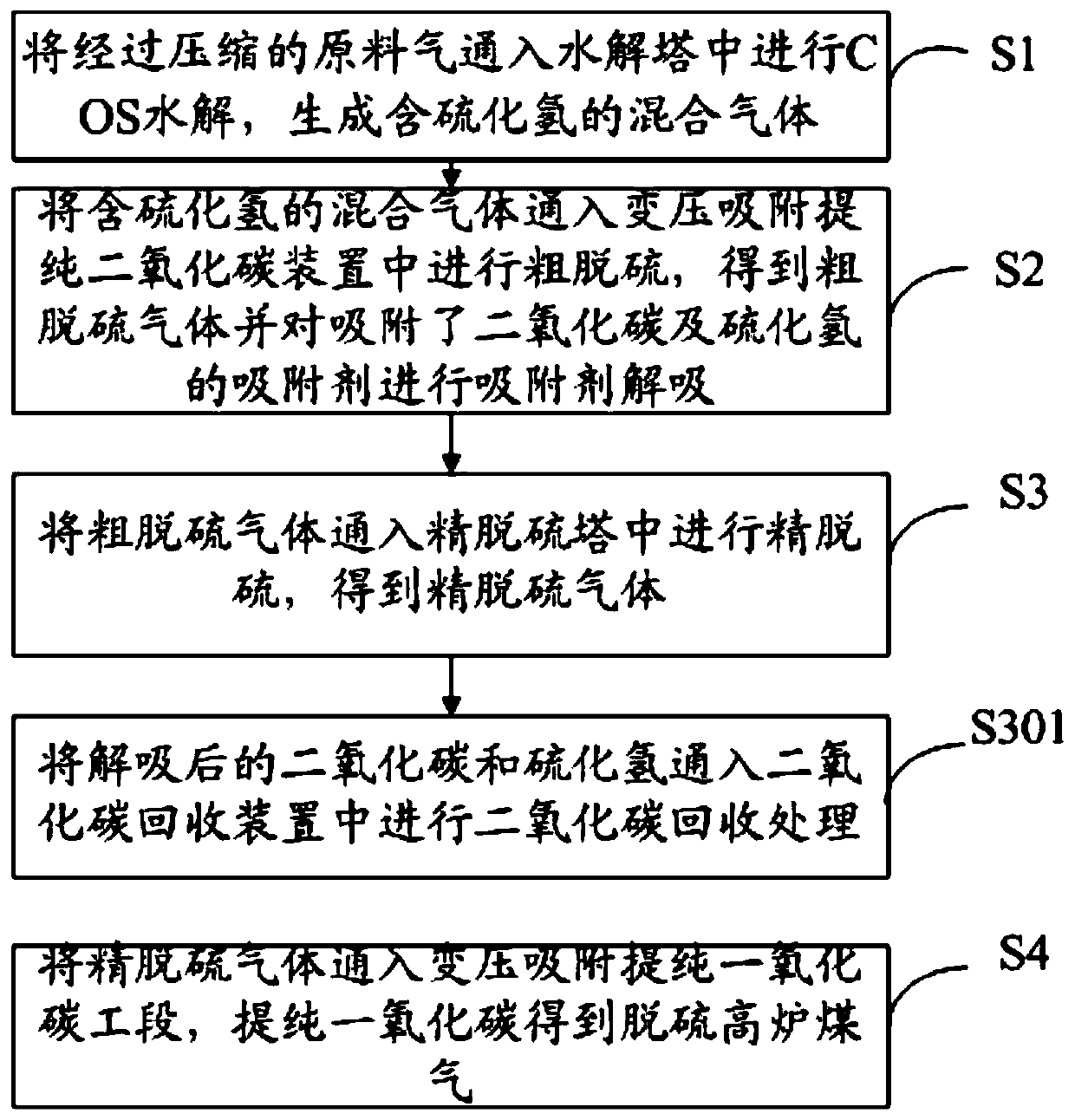
[0048] See figure 2 , figure 2 It is the schematic flow chart of the method of embodiment two, as figure 2 As shown, on the basis of Example 1, after desorbing the adsorbed carbon dioxide and hydrogen sulfide adsorbent, the blast furnace gas desulfurization method also includes:
[0049] S301. Pass the desorbed carbon dioxide and hydrogen sulfide into a carbon dioxide recovery device for carbon dioxide recovery treatment.
[0050] Among them, the carbon dioxide recovery device can recover carbon dioxide while separating carbon dioxide and hydrogen sulfide, and can reuse the recovered carbon dioxide. Carbon dioxide can be adsorbed by a carbon dioxide adsorbent to separate carbon dioxide and hydrogen sulfide. The carbon dioxide adsorbent can be silica gel or a molecular sieve corresponding to carbon dioxide adsorption. After separating hydrogen sulfide, desorb the adsorbent that has adsorbed carbon dioxide to recover carbon dioxide.
Embodiment 3
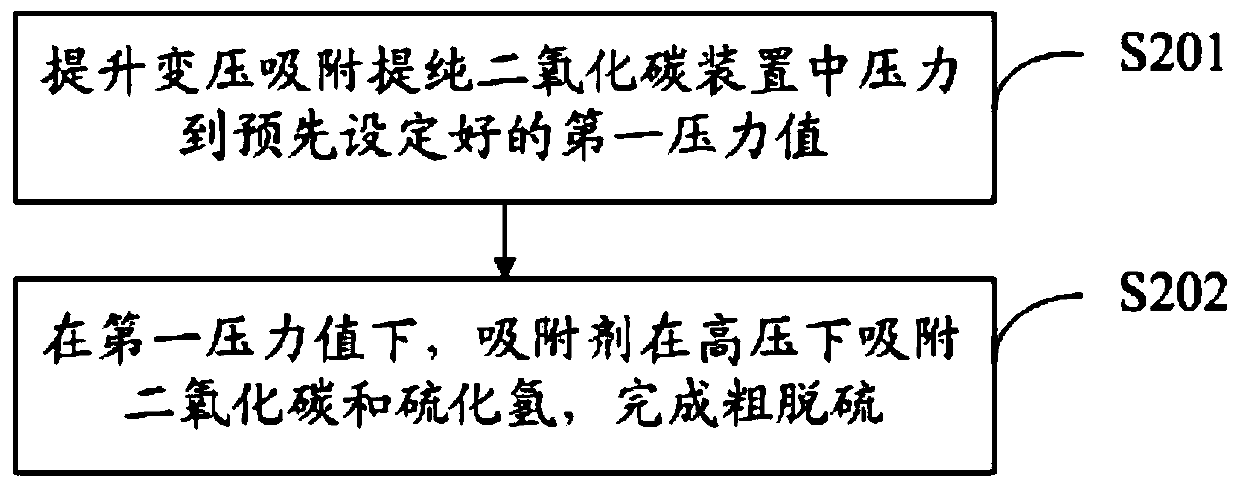
[0052] See image 3 , image 3 It is the schematic flow chart of the method of embodiment three, on the basis of embodiment one, such as image 3 As shown, the specific crude desulfurization includes the following steps:
[0053] S201. Raising the pressure in the pressure swing adsorption carbon dioxide purification device to a preset first pressure value;
[0054] S202. Under the first pressure value, the adsorbent adsorbs carbon dioxide and hydrogen sulfide under high pressure to complete crude desulfurization.
[0055] Wherein, the above-mentioned first pressure value is preset, which is convenient for operation, and the range of the above-mentioned first pressure value may be 0.15Mpa. The above crude desulfurization can be understood as the removal of carbon dioxide and hydrogen sulfide. Since there is no need to generate elemental sulfur from hydrogen sulfide, the desorption speed of the adsorbent will be faster, and solid waste will not be formed during the crude des...
PUM
 Abstract
Description
Claims
Application Information