Supercharge Your Innovation With Domain-Expert AI Agents!

Power shearing mechanism for hydraulic pump

A hydraulic pump and power technology, which is applied in the field of hydraulic plunger pumps, can solve the problems of low universality of hydraulic pumps, and achieve the effects of universality, application market improvement, and performance optimization

Active Publication Date: 2019-09-10
龙工(上海)精工液压有限公司
View PDF10 Cites 0 Cited by
  • Summary
  • Abstract
  • Description
  • Claims
  • Application Information

AI Technical Summary

Problems solved by technology

[0004] The technical problem to be solved by the present invention is: in the practical application of the hydraulic plunger pump, different engine manufacturers have the phenomenon of holding the car at low load and idling speed, which leads to the problem that the hydraulic pump is not very versatile in the selection of the engine.

Method used


Image

  • Power shearing mechanism for hydraulic pump
  • Power shearing mechanism for hydraulic pump

Examples


Embodiment

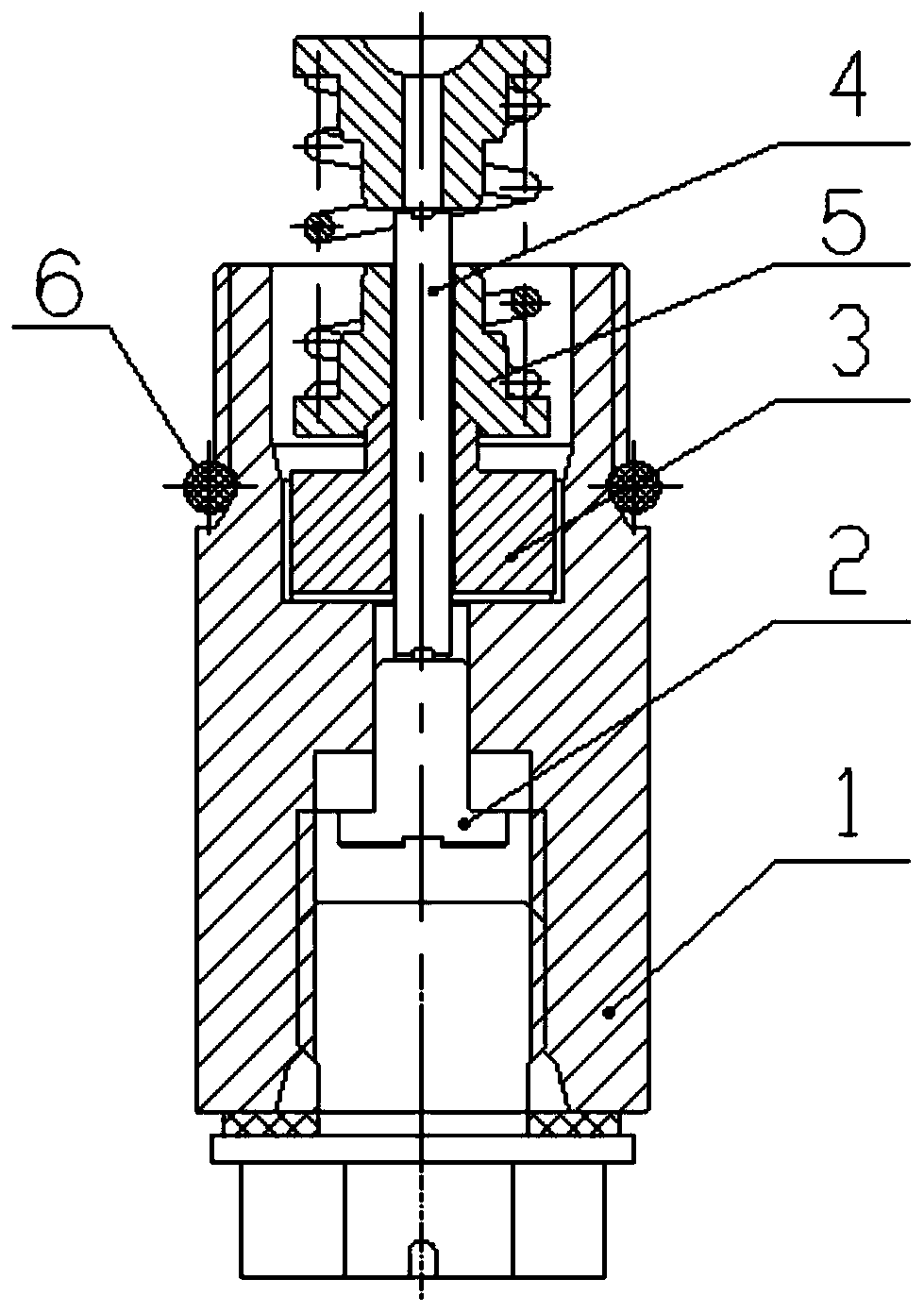
[0018] Such as figure 1 As shown, a hydraulic pump power shearing mechanism provided by the present invention includes:

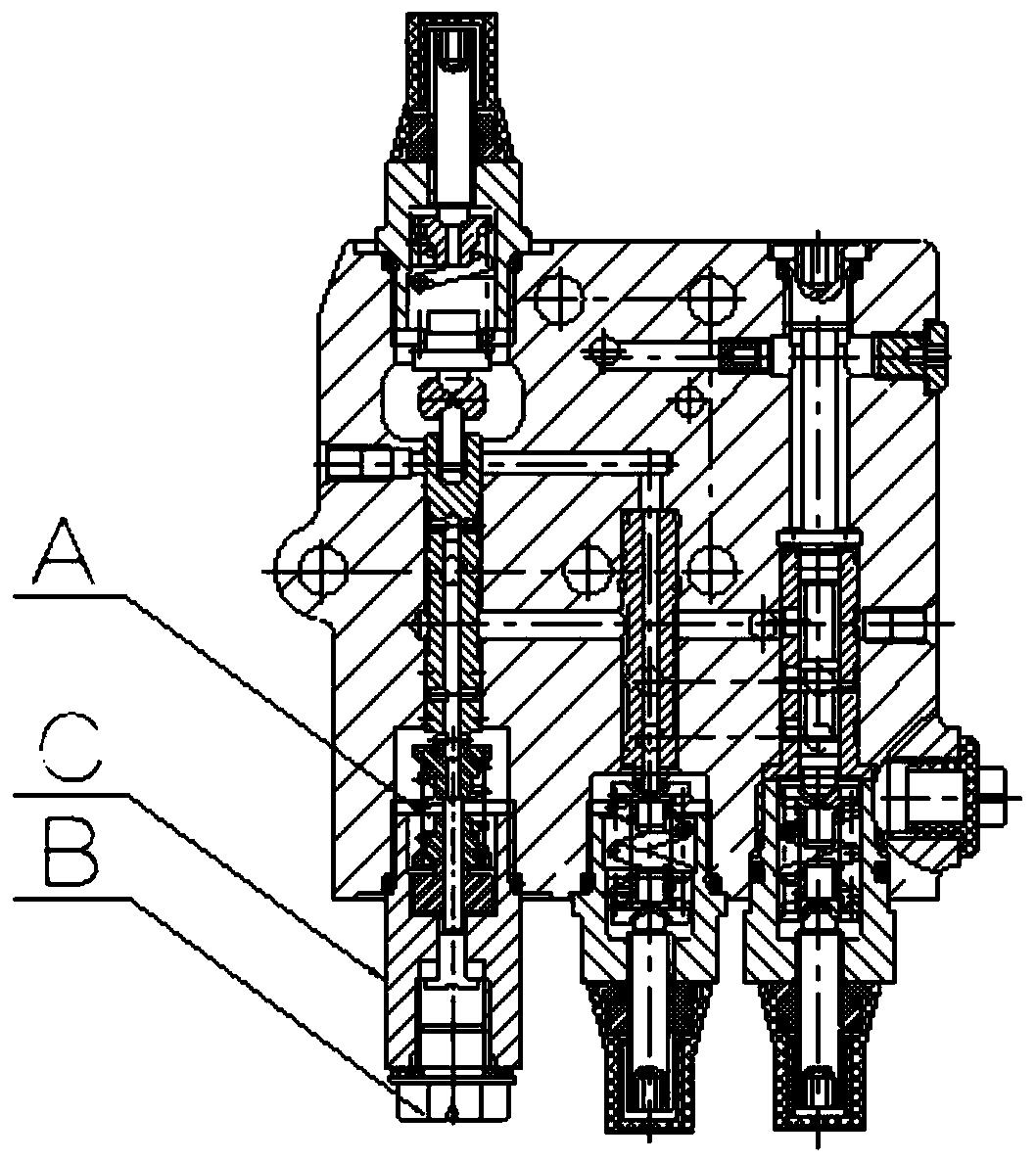
[0019] Nut 1, used to connect the electric proportional control valve body in the power control unit A and the pilot oil port B;

[0020] Top seat 2, used to control the flow in pilot oil port B;

[0021] The ejector rod 4 is used to control the top seat 2;

[0022] The spacer 3 is used to limit the ejector rod 4 in the nut 1, and the nut 1 is provided with a position-limiting structure matched with the spacer 3;

[0023] The spring seat 5 is used to reset the push rod 4.

[0024] The end of the nut 1 connected to the pilot oil port B is provided with a depression, and the top seat 2 is set in the depression; one end of the top seat 2 is set in the pilot oil port B, and the other end is connected with the ejector rod 4, and the ejector rod 4 passes through in turn. Through the spacer 3 and the spring seat 5, it is exposed from the end where the nut 1 is...


PUM


Abstract

The invention discloses a power shearing mechanism for a hydraulic pump. The power shearing mechanism is characterized by comprising a screw cap, a footstock, an ejector rod, a cushion block and a spring, wherein the screw cap is used for connecting an electric proportional control valve body in a power control unit with a pilot oil port; the footstock is used for controlling the flow rate in thepilot oil port; the ejector rod is used for controlling the footstock; the cushion block is used for enabling the ejector rod to be limited in the screw cap; the screw cap is internally provided witha limiting structure matched with the cushion block; the spring is fixedly arranged on a spring seat and is used for resetting the ejector rod. According to the power shearing mechanism disclosed by the invention, a structure of a hydraulic plunger pump control unit is optimized; the proportional change of a power value is realized by the electric proportional control valve and is used for matching with power performance of different engine manufactures; meanwhile, a power peak is kept unchanged, and normal working requirements are met. The power shearing mechanism realizes the generality of the hydraulic pump matching with engines from different manufacturers, so that the application market of the plunger pump is greatly expanded and the performance optimization of the hydraulic plunger pump is realized.

Description

technical field [0001] The invention relates to a mechanism capable of realizing hydraulic pump power shear, which belongs to the technical field of hydraulic plunger pumps. Background technique [0002] At present, most of the swash plate plunger pumps designed by well-known foreign hydraulic component manufacturers adopt constant power control. The constant power control function limits the maximum power of the system. The total power curve operation ensures that the product of pressure and flow (approximately the output power of the pump) is approximately a constant value. This function can ensure that the pump can protect the engine and the whole machine when it is working in super saturation. The existing hydraulic pump is equipped with a power control unit, and the electric proportional control valve body in the power control unit is directly connected to the pilot oil port, and the power of the hydraulic pump is controlled by controlling the flow in the oil port. The...

Claims


Application Information

Patent Timeline
Patent Type & Authority Applications(China)
IPC IPC(8): F04B1/26F04B49/22F04B53/10
CPCF04B1/26F04B49/22F04B53/10
Inventor 陈超钱绪马宗宇余红波
Owner 龙工(上海)精工液压有限公司
Features
  • R&D
  • Intellectual Property
  • Life Sciences
  • Materials
  • Tech Scout
  • Unparalleled Data Quality
  • Higher Quality Content
  • 60% Fewer Hallucinations
Learn More