Satellite borne dual-channel dual-beam InSAR flow gaging system

A dual-beam, dual-channel technology, applied in the field of spaceborne dual-channel dual-beam InSAR current measurement systems, can solve the problems of spatial inconsistency, no InSAR system, mean deviation, etc.

Active Publication Date: 2019-09-10
NANJING UNIV OF INFORMATION SCI & TECH
View PDF5 Cites 11 Cited by
  • Summary
  • Abstract
  • Description
  • Claims
  • Application Information

AI Technical Summary

Problems solved by technology

For the third dual-beam generation method, the direct consequence of using the "Burst" mode is the so-called "scallop effect" produced by "missing SAR azimuth data", which makes the amplitude of the SAR image change periodically in the azimuth direction, while This image "non-homogeneity" will not only produce spatial inconsistency in the "velocity uncertainty" of ocean current inversion, but also produce an "extra" velocity "mean deviation"
In addition, the "Burst" mode will also cause a certain "difference" in the SAR data corresponding to the "forward" and "backward" beams, which will have a negative impact on the inversion of the ocean current velocity vector
The second and third dual-beam generation methods are currently in the concept stage, and there is no actual InSAR system operating in orbit
[0006] In summary, there is no space-borne dual-beam InSAR current measurement system capable of commercial operation, and a new type of space-borne dual-beam InSAR system needs to be invented , to solve the problems existing in the "two-dimensional" velocity vector inversion of the sea surface current field

Method used


Image

  • Satellite borne dual-channel dual-beam InSAR flow gaging system
  • Satellite borne dual-channel dual-beam InSAR flow gaging system
  • Satellite borne dual-channel dual-beam InSAR flow gaging system

Examples


Embodiment Construction

[0080] The specific implementation manners of the present invention will be further described below in conjunction with the accompanying drawings, and this embodiment does not constitute a limitation to the present invention.

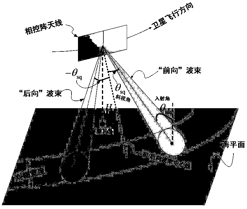
[0081] A spaceborne dual-channel dual-beam InSAR current measurement system is based on the existing "active phased array antenna" technology, such as figure 1 As shown, it includes a phased array radar antenna placed along the flight direction of the satellite and facing the sea surface in a side view. The phased array radar antenna is equipped with a number of phased array antenna radiating elements that radiate signals to the outer space . The system includes two beams, the forward beam and the backward beam, where the central incidence angles of the two beams are both θ inc , the oblique angle of the forward beam is θ sq , and the oblique angle of the backward beam is -θ sq .

[0082] 1) For phased array antenna radiating elements:

[0083] In ...


PUM


Abstract

The invention discloses a satellite borne dual-channel dual-beam InSAR flow gaging system, and relates to the technical field of ocean remote sensing. The satellite borne dual-channel dual-beam InSARflow gaging system comprises a phase-controlled radar antenna and a large broadband squint dual beam forming network module, wherein the phase-controlled radar antenna is provided with a plurality ofphase-controlled antenna radiation array elements; each phase-controlled antenna radiation array element is connected with an emitting / receiving assembly respectively; a broadband squint dual-beam forming network module is cascaded with the emitting / receiving assembly in a serial manner; when a radar transmits a signal, an intra-pulse beam switching method is adopted; during receiving of an echo signal, the whole antenna sub-hole aperture is divided into front antenna sub-apertures and back antenna sub-apertures equally in the flight direction of the radar; a simultaneous dual beam antenna directional diagram is formed on each antenna sub-aperture; and meanwhile, radar echo signals of a forward beam and a backward beam are received. Through adoption of the satellite borne dual-channel dual-beam InSAR flow gaging system, on the premise of preventing flow gaging accuracy and flow gaging space resolution from losing, an ocean current "two-dimension" speed vector wide swath measuring effect is achieved integrally.

Description

technical field [0001] The invention relates to the technical field of marine remote sensing, in particular to a space-borne dual-channel dual-beam InSAR current measurement system. Background technique [0002] The ocean covers about 70% of the earth's surface and is an important space for human survival and development as well as an important treasure house of resources. Ocean currents are one of the most important elements of the ocean. First of all, mastering the laws of ocean currents is of great scientific significance to marine science and climate change research. For example, ocean currents have an important influence and restrictive effect on the formation and change of climate and weather over the ocean: ocean currents flowing from low latitudes to high latitudes will cause water vapor to be transported upwards, increasing air humidity and producing precipitation; while ocean currents flowing from high latitudes to Ocean currents at low latitudes will produce temp...

Claims


Application Information

Patent Timeline
Patent Type & Authority Applications(China)
IPC IPC(8): G01S13/90G01S13/58
CPCG01S13/9023G01S13/9094G01S13/589
Inventor 刘保昌何宜军李秀仲陈忠彪
Owner NANJING UNIV OF INFORMATION SCI & TECH
Why Eureka
Try Eureka