Magnetic separation equipment and magnetic separation method for quartz sand

A technology of magnetic separation equipment and quartz sand, which is applied in chemical instruments and methods, magnetic separation, solid separation, etc., can solve the problems of difficulty in purifying quartz sand, incomplete dispersion and increasing the volume of magnetic separation devices, etc., to achieve increased Magnetic separation effect, good magnetic separation effect, effect of improving effect

Pending Publication Date: 2019-09-13
新沂市嘉新矿业有限公司
View PDF1 Cites 6 Cited by
  • Summary
  • Abstract
  • Description
  • Claims
  • Application Information

AI Technical Summary

Problems solved by technology

However, the traditional magnetic separation equipment has poor magnetic separation and separation effect, and it is difficult to achieve the purpose of purifying quartz sand.
[0004] The prior art CN207839187U protects a quartz sand dry-type magnetic separator. This technical solution realizes the magnetic separation of the quartz sand, but the magnetic separation is based on a semi-circular permanent magnet to separate the magnetic substance from the quartz sand. The disadvantage is that the magnetic substance When transported to the right end of the magnetic separation layer by the conveyor belt, some magnetic substances will be transported to the upper part of the magnetic separation device again, and cannot completely fall to the waste sand discharge port below, and the purification effect is not good.
In addition, the uniform dispersion of quartz sand in the prior art is realized through the stirring layer. By setting the stirring layer, the volume of the magnetic separation device is increased, and the dispersion cannot be completely uniform.

Method used


Image

  • Magnetic separation equipment and magnetic separation method for quartz sand
  • Magnetic separation equipment and magnetic separation method for quartz sand
  • Magnetic separation equipment and magnetic separation method for quartz sand

Examples


Embodiment approach 1

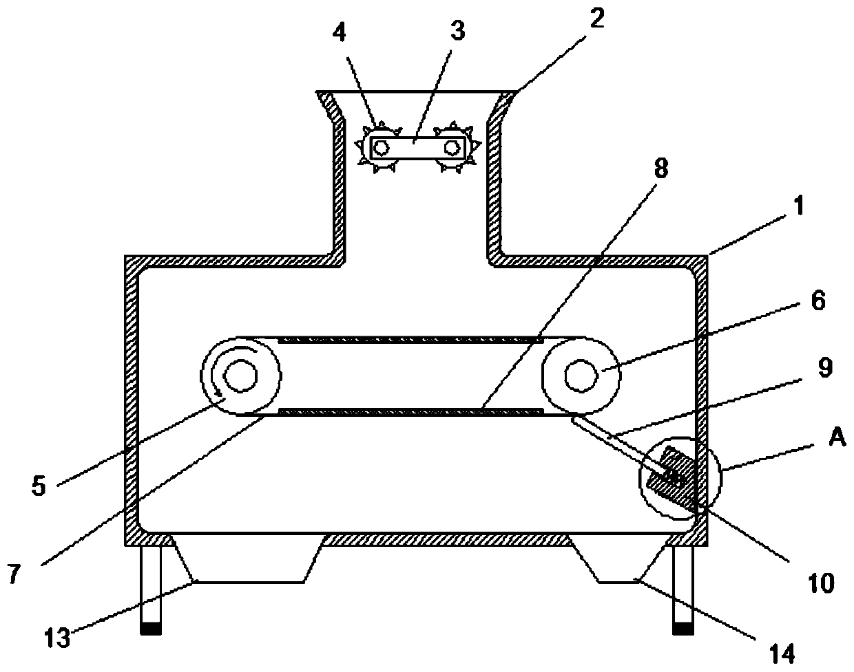
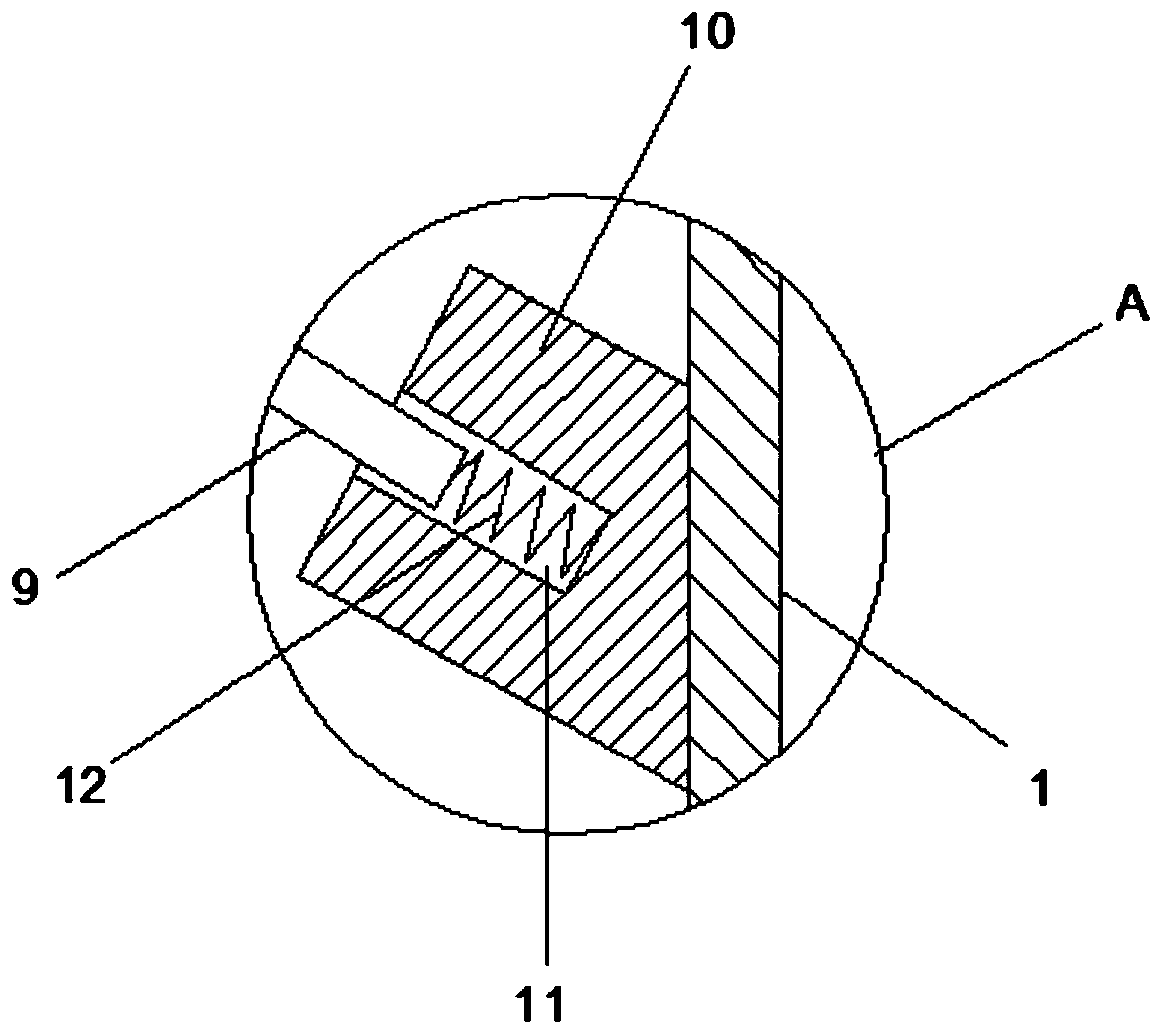
[0032] see Figure 1-2 A preferred embodiment of the magnetic separation equipment for quartz sand of the present invention shown, the magnetic separation equipment includes a magnetic separation bin 1 and a feed hopper 2 fixedly connected to the top of the magnetic separation bin 1, below the feed hopper 2 It communicates with the magnetic separation bin 1, so that the quartz sand that needs to be magnetically separated can be sent into the magnetic separation bin 1 through the feed hopper 2 for magnetic separation. In order to obtain a better magnetic separation effect, it is necessary to crush and pulverize the coarse quartz sand. For this reason, a crushing device is provided in the feed hopper 2. The crushing device includes a crushing motor 3 and a crushing roller 4, and the crushing roller There are two of 4, and they are relatively arranged in the feed hopper 2, and are connected with the crushing motor 3 outside the feed hopper 2, so that the quartz coarse sand enteri...

Embodiment approach 2

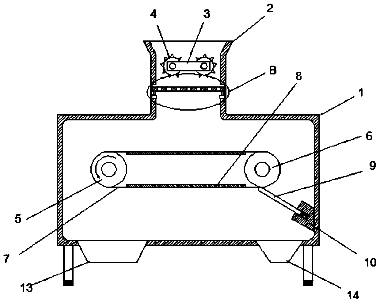
[0036] see Figure 3-4Shown is the second embodiment of the magnetic separation equipment for quartz sand of the present invention. The difference between this embodiment and the first embodiment is that in order to disperse the crushed quartz sand evenly on the conveyor belt, a A vibrating device is provided, and the vibrating device includes a vibrating motor 15 and a sieve plate 16 connected to the output shaft of the vibrating motor 15. The sieve plate 16 is evenly distributed with sieve holes 17, and the inner wall of the feed hopper 2 is provided with concave holes. groove 18, the vibration motor 15 is fixed on the bottom wall of the groove 18, and the sieve plate 16 is arranged in the groove 18, so that when the broken quartz sand needs to be dispersed, the vibration motor 15 is started The vibrating motor 15 drives the sieve plate 16 to vibrate. At this time, the quartz sand falling on the sieve plate 16 will be evenly dispersed on the sieve plate 16 due to the vibrati...

Embodiment approach 3

[0039] see Figure 5 The second embodiment of the magnetic separation equipment for quartz sand of the present invention shown, this embodiment is different from the second embodiment in that: a blower 19 is arranged on the left side of the magnetic scraping device, and the blower 19 is connected with Air blast head 20, said air blast head 20 is arranged inclined to the left, like this, can blow off the remaining quartz sand on the transmission belt 7 by air blast head 20, thereby improves the collection amount of quartz sand.

[0040] The working principle of the present invention is: when in use, the quartz sand is added into the feed hopper 2, first the coarse quartz sand is changed into fine quartz sand through the crushing treatment of the crushing device, and then evenly dispersed on the conveyor belt 7 under the action of the vibrating device. On the upper surface, the electromagnet 8 in the conveyor belt 7 attracts the magnetic material in the quartz sand. Under the ac...


PUM


Abstract

The invention discloses magnetic separation equipment and a magnetic separation method for quartz sand. The equipment comprises a magnetic separation bin and a feeding hopper fixedly connected to thetop of the magnetic separation bin; a crushing device is arranged in the feeding hopper, and comprises a crushing motor and a crushing roller; a magnetic separation device is arranged in the magneticseparation bin; the magnetic separation device comprises a driving wheel, a driven wheel and a conveying belt connected to the driving wheel and the driven wheel; electromagnets are arranged on the upper side and the lower side in the conveying belt; the left side of the magnetic separation bin is provided with a magnetic scraping device; the magnetic scraping device comprises a magnetic scrapingplate and a base connected with the magnetic scraping plate in a sliding mode; the base is fixed on the inner side wall of the magnetic separation bin; a sliding groove is formed in the top of the base; and one end of the magnetic scraping plate is connected in the sliding groove in a sliding mode through a spring, and the other end of the magnetic scraping plate abuts against the conveying belt.The magnetic separation equipment has the advantages that the magnetic separation effect is good, magnetic substances in the quartz sand can be effectively removed, and the purity of the quartz sand is improved.

Description

technical field [0001] The invention relates to the technical field of magnetic separation equipment, in particular to a magnetic separation equipment for quartz sand and a magnetic separation method thereof. Background technique [0002] Quartz sand is a non-metallic mineral, a hard, wear-resistant, chemically stable silicate mineral, and its main mineral component is SiO 2 , the color of quartz sand is milky white, or colorless and translucent, with a hardness of 7. Quartz sand is an important industrial mineral raw material, non-chemical dangerous goods, widely used in glass, casting, ceramics and refractory materials, ferrosilicon smelting, metallurgical solvents , metallurgy, construction, chemical industry, plastics, rubber, abrasives and other industries. [0003] The purification of quartz sand is one of the more critical processes. At present, magnetic separation is mostly used for purification of quartz sand to remove magnetic ore in quartz sand and increase the c...

Claims


Application Information

Patent Timeline
Patent Type & Authority Applications(China)
IPC IPC(8): B03C1/18B03C1/005
CPCB03C1/005B03C1/18
Inventor 郁春晓
Owner 新沂市嘉新矿业有限公司
Why Eureka
Try Eureka