Energy-saving continuity liquid fodder filling machine
A liquid feed and filling machine technology, applied in liquid bottling, liquid processing, packaging, etc., can solve the problems of long time, slow feeding speed, waste, etc., to ensure flexibility, stability, and stable filling Effect
- Summary
- Abstract
- Description
- Claims
- Application Information
AI Technical Summary
Problems solved by technology
Method used
Image
Examples
Embodiment 1
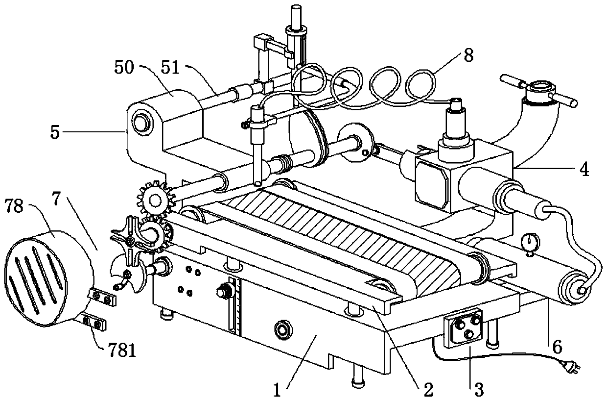
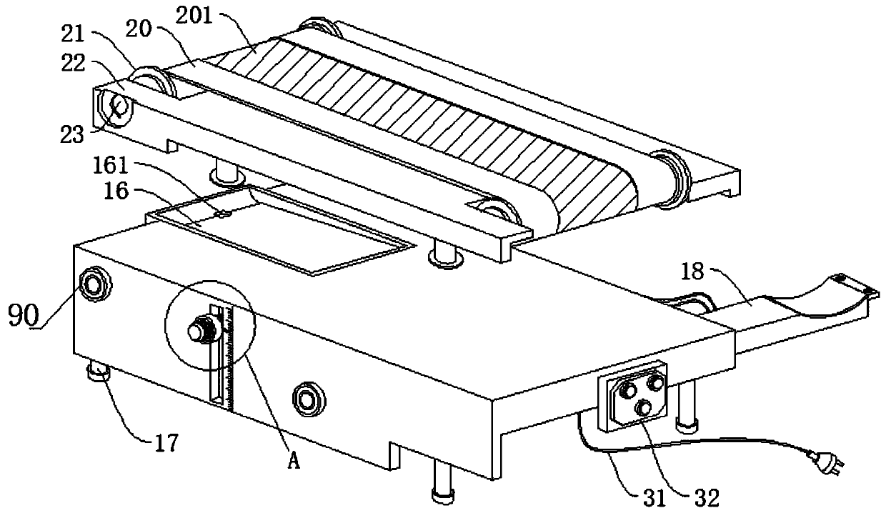
[0030] The present invention provides an energy-saving continuous liquid feed filling machine through improvement, as shown in the drawings of the description, it can be implemented in the following manner; including base 1, workbench 2 and power supply 3, workbench 2 and power supply 3 Correspondingly arranged on the top and one side of the base 1, one side of the base 1 is connected with a support arm 18, and the support arm 18 is equipped with a booster mechanism 6, and the three sides along the counterclockwise direction of the base 1 are respectively provided with There are feeding system 4, motion mechanism 5 and transmission assembly 7; the base 1 and the bottom of the workbench 2 are equipped with support feet 17, and the workbench 2 is erected on the top of the base 1 and fixedly connected with the base 1 through the support feet 17 The power supply 3 includes a 380V power cord 31 and a dual-control switch 32, and the 380V power cord 31 is connected in series with the ...
Embodiment 2
[0037] The present invention provides an energy-saving continuous liquid feed filling machine through improvement. The difference from the first embodiment is that the booster mechanism 6 includes an air pump 61, an air pump controller 62, a pressure gauge 63, an air pipe 64 and a one-way valve 65 , the air pump 61 is installed on the support arm 18; the pressure gauge 63 is installed on the top of the air pump 61, the one-way valve 65 is embedded and installed on one end of the right piston cylinder 44, and the air pipe 64 is respectively connected to the one-way valve 65 and the air pump 61, and the air pump controller 62 There is a power knob for adjusting the air volume of the air pump 61, which is used to adjust the power of the compressor in the air pump 61 to achieve the purpose of adjusting the strength of the compressed air pressure. After the air pump 61 is started, the high-pressure gas generated by the internal air compressor enters the right side through the air pip...
Embodiment 3
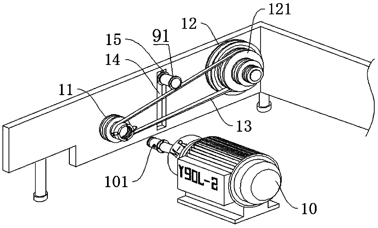
[0041] The difference from Embodiments 1 and 2 is that the speed regulating roller 15 is composed of a screw rod 151 and a fastening bolt 152. One end of the screw rod 151 and the fastening bolt 152 are screwed together and clamped and fixed on the limit hole 14. The screw rod 151 The other end of the base is connected to the flange bearing 91; the motor 10, the first pulley 11, the second pulley 12 and the belt 13 are respectively installed inside the base 1, and the first pulley 11, the second pulley 12 and the flange bearing 91 pass through The belt 13 drives; the front end of the surface of the base 1 is embedded with a receiving box 16, and the inner bottom wall of the receiving box 16 is provided with a filter hole 161; the first pulley 11 and the second pulley 12 are composed of several speed regulating discs with different diameters 121 are coaxially connected; the transmission shaft end of the motor 10 is provided with a flange sleeve 101, and the flange sleeve 101 is ...
PUM
 Abstract
Description
Claims
Application Information
 - R&D
- Intellectual Property
- Life Sciences
- Materials
- Tech Scout
- Unparalleled Data Quality
- Higher Quality Content
- 60% Fewer Hallucinations
Browse by: Latest US Patents, China's latest patents, Technical Efficacy Thesaurus, Application Domain, Technology Topic, Popular Technical Reports.
© 2025 PatSnap. All rights reserved.Legal|Privacy policy|Modern Slavery Act Transparency Statement|Sitemap|About US| Contact US: help@patsnap.com


