Photoelectric combined type geophone and detecting system

A technology of geophones and detection systems, applied in seismic signal receivers, seismology, geophysical measurement, etc., can solve the problems of short response time, inability to measure, continuous power supply, etc., and achieve reasonable structural design, high precision and High reliability and accuracy

Active Publication Date: 2019-09-17
SHANDONG UNIV OF SCI & TECH
View PDF9 Cites 2 Cited by
  • Summary
  • Abstract
  • Description
  • Claims
  • Application Information

AI Technical Summary

Problems solved by technology

Most of the existing geophones are electromagnetic. Electromagnetic geophones have the properties of strong resistance to external interference, short response time, and strong linearity. The acceleration equivalent noise of existing electrical geophones or seismometers is generally in the range of μg·Hz -1 / 2 even ng·Hz -1 / 2 Below the order of magnitude, the disadvantage of electromagnetic detectors is that continuous power supply is required for measurement, and it is difficult to apply in harsh monitoring environments
The existing geophones also have optical fiber type, which can make up for the shortcomings of the electromagnetic type, but the measurement range of the optical fiber type geophone is 5-800Hz, and it is impossible to measure the vibration of rockburst (frequency 0-10Hz)

Method used


Image

  • Photoelectric combined type geophone and detecting system
  • Photoelectric combined type geophone and detecting system
  • Photoelectric combined type geophone and detecting system

Examples


Embodiment Construction

[0031] The technical solutions in the embodiments of the present invention will be clearly and completely described below in conjunction with the drawings in the present invention. Apparently, the described embodiments are only some of the embodiments of the present invention, not all of them. Based on the embodiments of the present invention, all other embodiments obtained by persons of ordinary skill in the art without making creative efforts belong to the protection scope of the present invention.

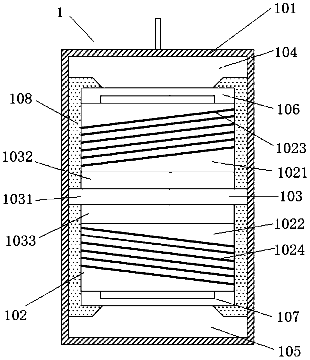
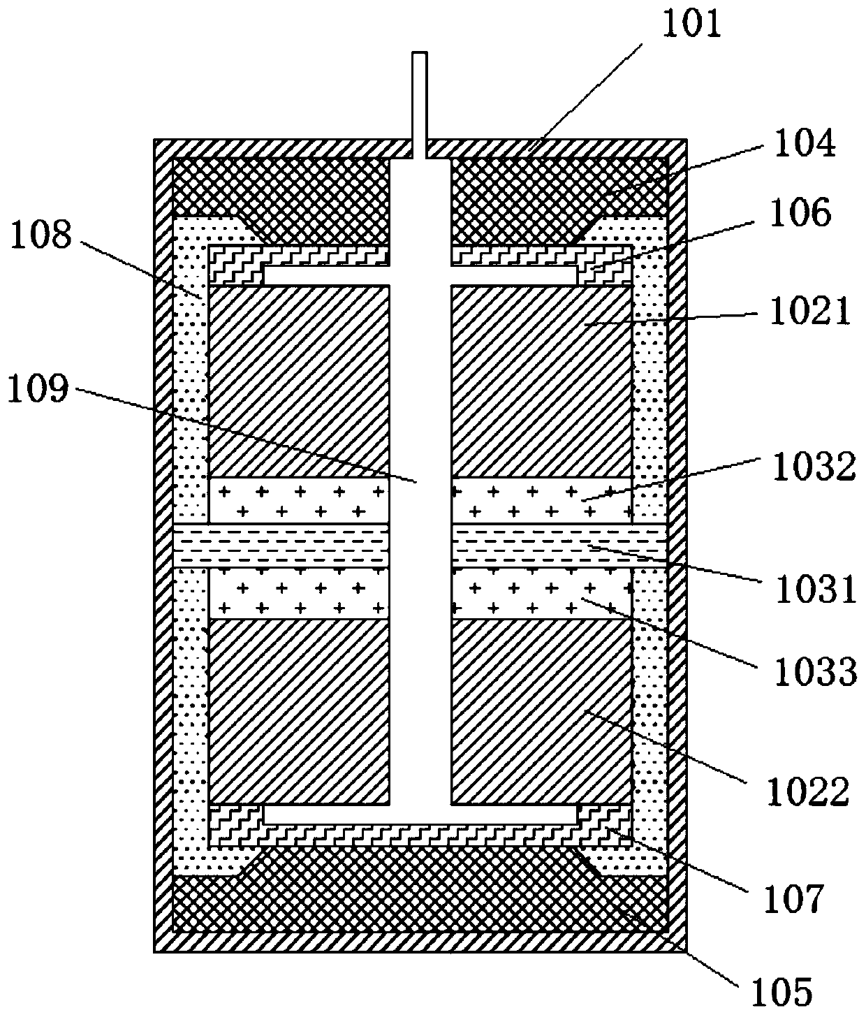
[0032] Such as figure 1 and figure 2 As shown, a photoelectric composite geophone 1 according to the embodiment of the present invention includes a housing 101, an optical fiber detection assembly 102 and a piezoelectric detection assembly 103 installed inside the housing 101, wherein:

[0033] The optical fiber detection assembly 102 includes a first compliant cylinder 1021, a second compliant cylinder 1022 arranged on a coaxial line, and a first optical fiber 1023 fixedly wo...


PUM


Abstract

The invention relates to the technical field of seismic detection, and particularly discloses a photoelectric combined type geophone. The geophone comprises a shell, an optical fiber detection component and a piezoelectric detection component, wherein the optical fiber detection component comprises a first compliant cylinder, a second compliant cylinder, a first optical fiber and a second optical fiber, wherein the first compliant cylinder and the second compliant cylinder are coaxially arranged, the first optical fiber is clockwise fixedly wound on the first compliant cylinder, and the second optical fiber is anticlockwise fixedly wound on the second compliant cylinder; and the piezoelectric detection component is located between the lower end face of the first compliant cylinder and the upper end face of the second compliant cylinder and comprises a detection substrate, a first piezoelectric patch, a second piezoelectric patch and an electric signal transmission line, wherein the first piezoelectric patch is fixedly arranged on the upper surface of a detection substrate, the second piezoelectric patch is fixedly arranged on the lower surface of the detection substrate, and the electric signal transmission line is electrically connected with the first piezoelectric patch and the second piezoelectric patch. According to the photoelectric combined type geophone provided by the invention, seismic waves are measured simultaneously by combining the optical fiber detection component and the piezoelectric detection component, so that the actual parameters of vibration signals can be obtained more accurately, and higher accuracy and reliability are achieved.

Description

technical field [0001] The invention relates to the technical field of earthquake detection, in particular to a photoelectric composite geophone and a detection system. Background technique [0002] Seismic exploration is currently one of the most commonly used physical detection methods for petroleum exploration and coal mines. It mainly uses the vibration signals generated by artificial seismic sources in the formation, and places seismometers at different positions from the seismic source to collect vibration signals, and then performs corresponding processing on the signals. data processing. [0003] Geophones are vibration sensors commonly used in seismic exploration. As the front-end equipment for signal reception and acquisition, their characteristic parameters directly affect the accuracy of seismic data acquisition results. Most of the existing geophones are electromagnetic. Electromagnetic geophones have the properties of strong resistance to external interference...

Claims


Application Information

Patent Timeline
Patent Type & Authority Applications(China)
IPC IPC(8): G01V1/18G01V1/22
CPCG01V1/181G01V1/226
Inventor 刘奇陈绍杰尹大伟冯帆
Owner SHANDONG UNIV OF SCI & TECH
Why Eureka
Try Eureka