
Three-pole sputtering ion pump

An ion pump and sputtering technology, applied in the direction of ion diffusion discharge tube, particle separation tube, etc., can solve the problems of rapid drop in pumping speed, achieve high pumping speed, increase sputtering output, and low maintenance cost

Active Publication Date: 2019-09-17
NORTHEASTERN UNIV
View PDF4 Cites 1 Cited by
  • Summary
  • Abstract
  • Description
  • Claims
  • Application Information

AI Technical Summary

Problems solved by technology

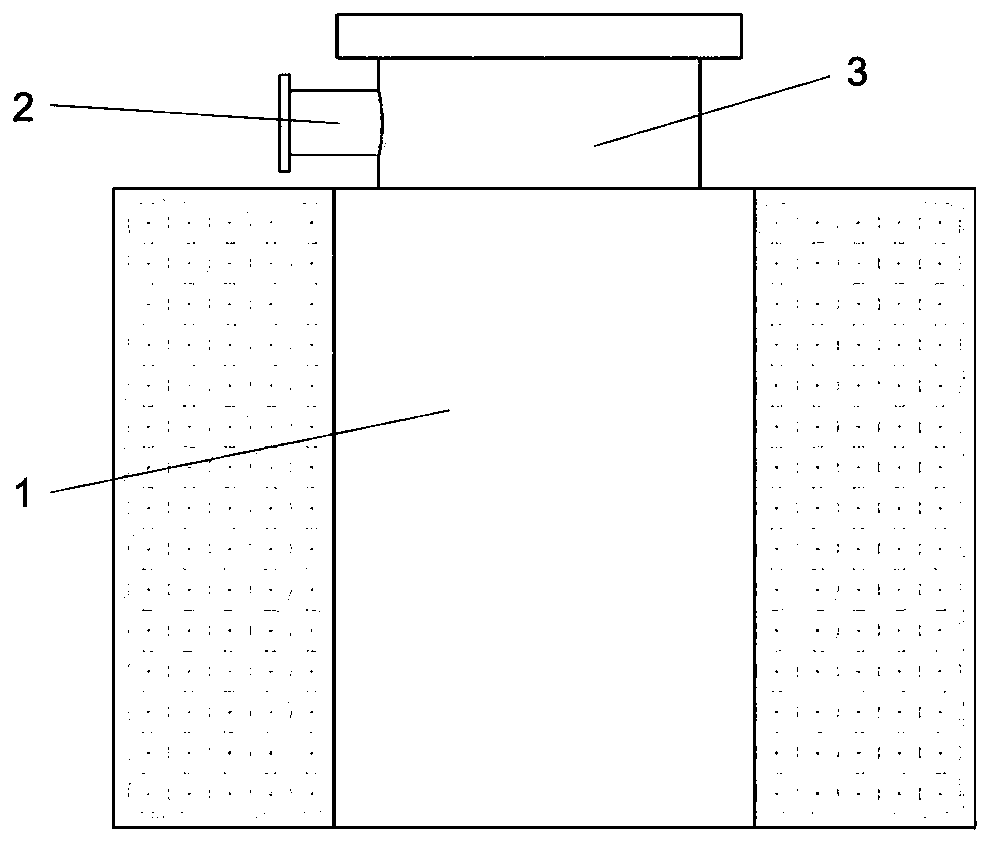
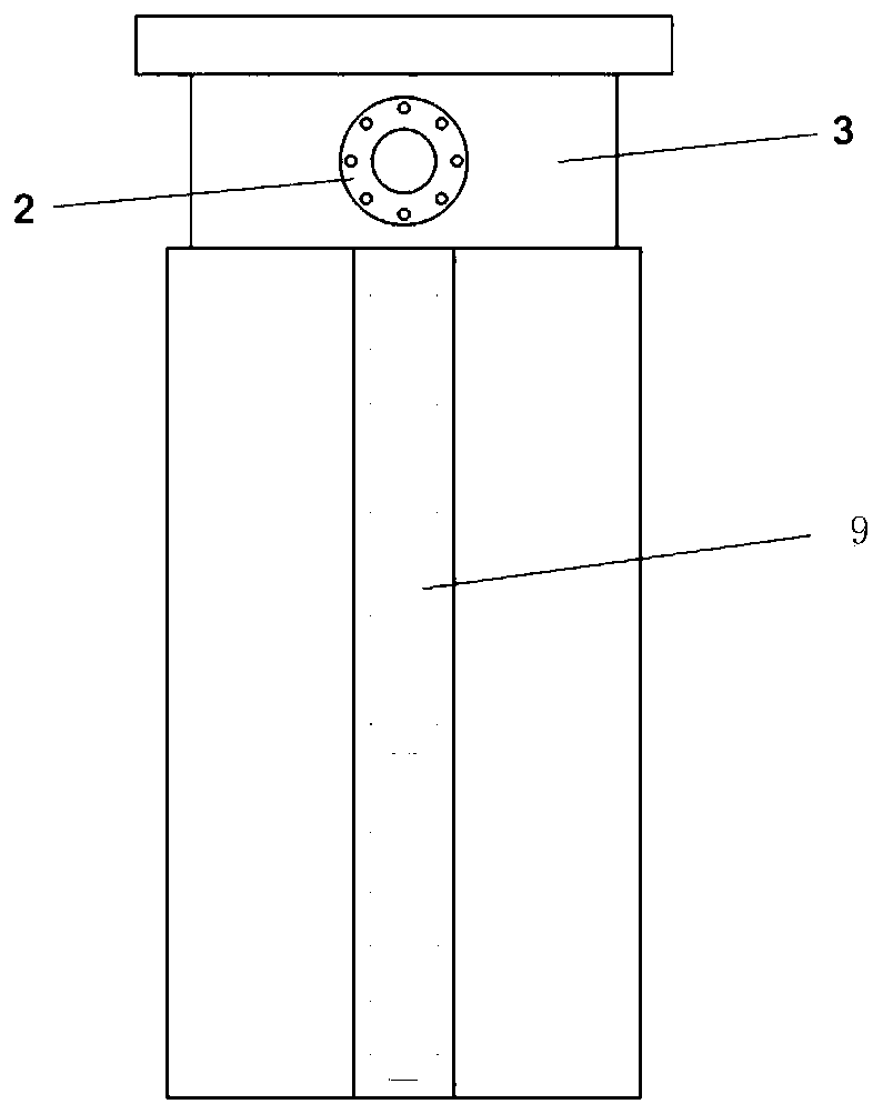
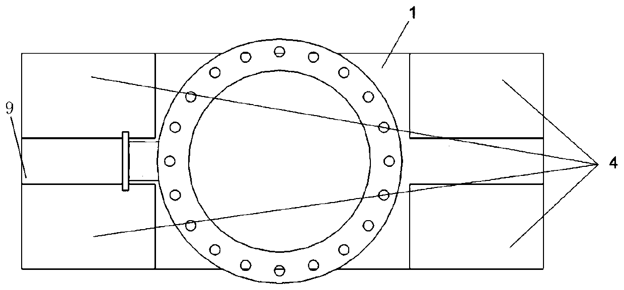
[0004] In order to solve the technical problems of the sputtering ion pump in the prior art, such as the rapid decrease in the pumping speed when the vacuum degree is raised to ultra-high vacuum, the present invention provides a three-pole sputtering ion pump, which improves the efficiency of the positive ion incident on the cathode plate. angle, and the pumping speed of the sputter ion pump under high vacuum and ultra-high vacuum conditions

Method used


Image

  • Three-pole sputtering ion pump
  • Three-pole sputtering ion pump
  • Three-pole sputtering ion pump

Examples


Embodiment Construction

[0035] The following will clearly and completely describe the technical solutions in the embodiments of the present invention with reference to the accompanying drawings in the embodiments of the present invention. Obviously, the described embodiments are only part of the embodiments of the present invention, not all of them. In the description of the present invention, it should be noted that the orientation or positional relationship indicated by the terms "upper", "lower", "inner", "outer", "top" etc. is based on the orientation or positional relationship shown in the drawings , is only for the convenience of describing the present invention and simplifying the description, but does not indicate or imply that the referred device or element must have a specific orientation, be constructed and operated in a specific orientation, and thus should not be construed as limiting the present invention. The terms "first" and "second" are used for descriptive purposes only, and should ...


PUM


Abstract

The invention discloses a three-pole sputtering ion pump, and belongs to the technical field of vacuum obtaining equipment. The three-pole sputtering ion pump comprises a shell with an air inlet pipe arranged at the top; a plurality of permanent magnets arranged outside the shell; and M cavities and N air exhaust assemblies. The cavities and the air exhaust assemblies are communicated with the side wall of the shell, M is equal to N, the N air exhaust assemblies are arranged in the cavities in a one-to-one mode. Each air exhaust assembly comprises an anode cylinder array, a plurality of anode needles and two parallelly arranged cathode plates, wherein the anode cylinder array is arranged between the two parallelly arranged cathode plates, the anode needles vertically penetrate through the cathode plates, and the positions of the anode needles correspond to the axes of the anode cylinders in the anode cylinder array. The permanent magnets are in contact with the outer walls of the cavities, and the positions of the permanent magnets correspond to the positions of the cathode plates in the adjacent cavity. According to the three-pole sputtering ion pump, the angle of the positive ion emitted into the cathode plates is increased, and the pumping speed of the sputtering ion pump under the conditions of high vacuum and ultrahigh vacuum is increased.

Description

technical field [0001] The invention relates to the technical field of vacuum obtaining equipment, in particular to a three-pole sputtering ion pump. Background technique [0002] The concept of sputtering ion pump was proposed by Gurewitsch and Westendorp in 1954. It pumps gas through the Penning discharge process under vacuum conditions and the continuous burial of active gas by titanium atoms. It has the characteristics of no oil, no pollution, no rotation, With the advantages of no vibration, simple structure and high ultimate vacuum, it is widely used in various ultra-high vacuum scientific research devices and industrial equipment. The industries involved include accelerators, synchrotron radiation sources, high-power laser research, surface physics, material science, and space. Simulation, electron microscope, mass spectrometer, vacuum calibration, vacuum smelting, vacuum coating, semiconductor application equipment, vacuum electronic devices, etc. [0003] With the ...

Claims


Application Information

Patent Timeline
Patent Type & Authority Applications(China)
IPC IPC(8): H01J41/12H01J41/18
CPCH01J41/12H01J41/18
Inventor 王晓冬黄海龙宁久鑫
Owner NORTHEASTERN UNIV
Learn More