Steel-aluminum joint welding device

A welding device, steel and aluminum technology, applied in the direction of auxiliary devices, welding equipment, welding equipment, etc., can solve the problems of difficult direct welding of aluminum and steel, performance degradation of welding joints, deformation of welding joints, etc., and achieve the reduction of brittle compounds The effect of forming, reducing welding time and improving welding effect

Inactive Publication Date: 2019-09-20
ANHUI UNIVERSITY OF TECHNOLOGY AND SCIENCE
View PDF5 Cites 5 Cited by
  • Summary
  • Abstract
  • Description
  • Claims
  • Application Information

AI Technical Summary

Problems solved by technology

[0004] The object of the present invention is to provide a steel-aluminum joint welding device to solve the problem that the existing steel-aluminum joint welding proposed in the background art has a large difference in the metal properties of steel and aluminum, resulting in poor welding performance between steel and aluminum. The main problems are: aluminum and steel are difficult to weld directly because of their different melting points and densities. The melting point of steel is higher than that of aluminum. When aluminum is melted into liquid, the steel is still in solid state. Secondly, the density problem is when the steel is melted. , the liquid aluminum will float on the molten steel. When the liquid is cooled, the components they weld are not uniform, resulting in a decrease in the performance of the welded joint, and the thermal conductivity of steel and aluminum is very different, which is prone to deformation and cracks in the welded joint. Reduce the brittle compounds produced by the steel-aluminum joints during the welding process and affect the strength of the steel-aluminum joints, often increasing the time required for steel-aluminum joint welding, but it is easy to produce air bubbles at the joint position due to uneven heating of the steel-aluminum joints and affect the welding effect question

Method used


Image

  • Steel-aluminum joint welding device
  • Steel-aluminum joint welding device
  • Steel-aluminum joint welding device

Examples


Embodiment Construction

[0023] The following will clearly and completely describe the technical solutions in the embodiments of the present invention with reference to the accompanying drawings in the embodiments of the present invention. Obviously, the described embodiments are only some, not all, embodiments of the present invention. Based on the embodiments of the present invention, all other embodiments obtained by persons of ordinary skill in the art without making creative efforts belong to the protection scope of the present invention.

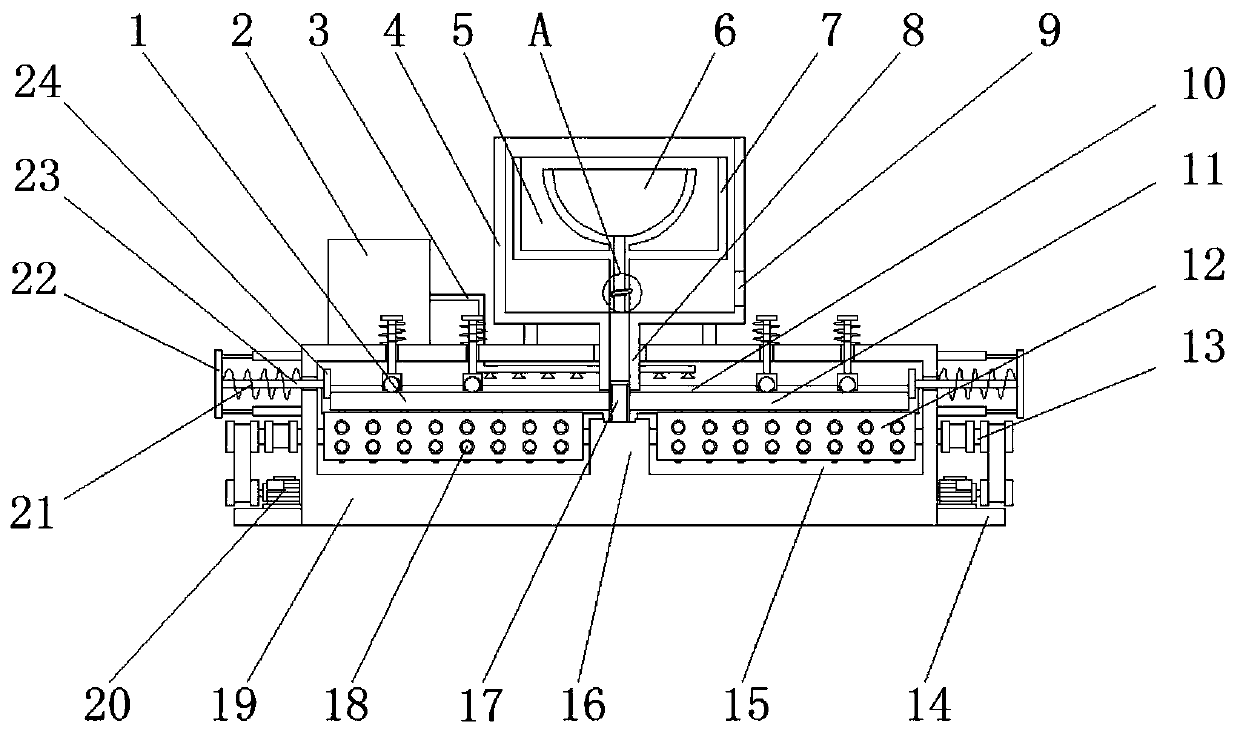
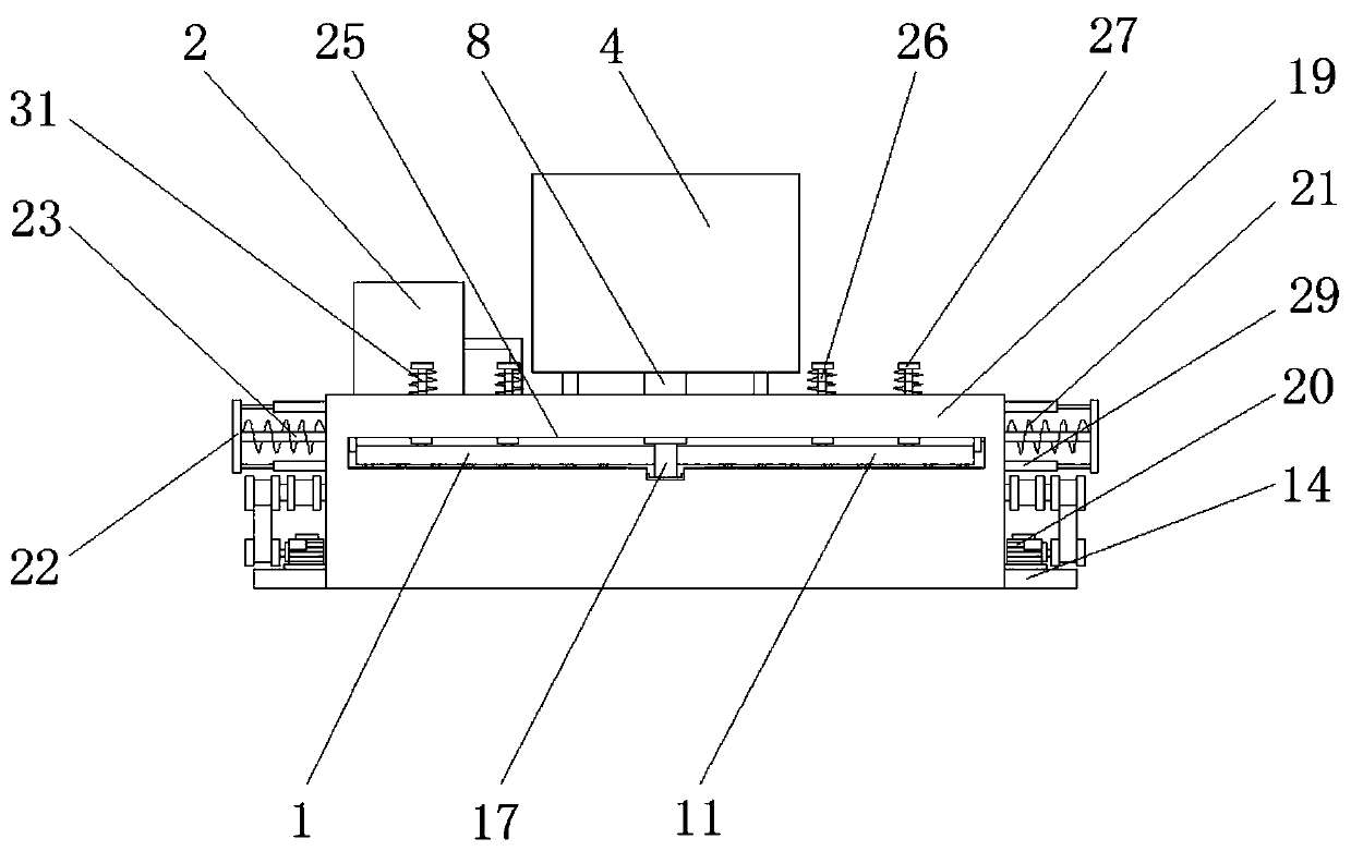
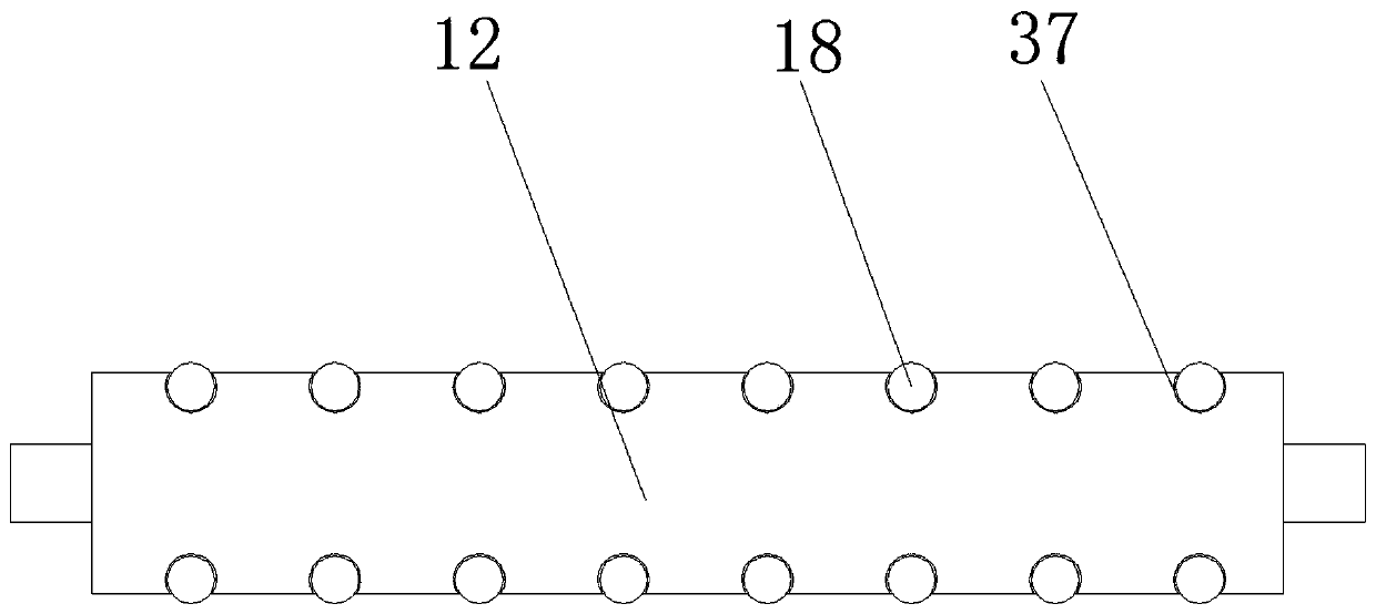
[0024] see Figure 1-7, an embodiment provided by the present invention: a steel-aluminum joint welding device, including a protective seat 4, a heating seat 6, a conveying roller 12, a mounting groove 15 and a housing 19, and the housing 19 is provided with a mounting groove 15 inside, One side of the housing 19 at the position of the installation groove 15 is provided with a feed port 25, the other side of the housing 19 at the position of the installation g...


PUM

PropertyMeasurementUnit
thicknessaaaaaaaaaa

Abstract

The invention discloses a steel-aluminum joint welding device. The steel-aluminum joint welding device comprises a protective base, a heating base, conveying rollers, mounting grooves and a shell. The shell is internally provided with the mounting grooves. A feed port is arranged on one side of the sell at the mounting grooves. According to the steel-aluminum joint welding device, a thin copper plate is arranged between a steel plate and an aluminum alloy plate; the aluminum alloy plate and the steel plate make contact with a material guide tube through the thin copper plate; on the one hand, the steel plate and the thin copper plate are isolated through limiting of the thin copper plate, and the situation that the steel plate and the aluminum alloy plate make contact with each other and have a reaction in the heating process and the welding quality is affected by brittle compounds generated from the reaction is avoided; and on the other hand, the thin copper plate achieves the heat conduction effect and conducts heat generated from a heating barrel to the welding ends of the aluminum alloy plate and the steel plate through a delivery tube, a material guide tube and the thin copper plate in sequence to achieve the preheating effect on the steel plate and the aluminum alloy plate. The influence of bubbles generated from uneven heating in the welding process on the welding quality is reduced.

Description

technical field [0001] The invention relates to the field of welding technology, in particular to a steel-aluminum joint welding device. Background technique [0002] Steel-aluminum joints are widely used in the pipeline configuration of low-temperature liquefaction equipment, especially for liquefied natural gas equipment. The main equipment heat exchanger of low-temperature liquefaction cold box generally adopts aluminum flip-fin structure because it has a heat exchange area Large, simple in structure, small in size and low in cost, while the most widely used material of low temperature valves for the adjustment and control of piping systems is stainless steel. Connection, also because the medium in the pipeline (liquid air, liquid oxygen, liquid nitrogen, liquid argon, liquefied natural gas and other refrigerants) operates at a low temperature of more than minus 100 degrees, metal thermal expansion and contraction deformation can easily cause bolts to loosen, resulting in...

Claims


Application Information

Patent Timeline
Patent Type & Authority Applications(China)
IPC IPC(8): B23K31/02B23K37/00B23K37/04B23K103/20
CPCB23K31/02B23K37/00B23K37/003B23K37/0408B23K2103/20
Inventor 邢昌王刚桂凯旋曹雪龙
Owner ANHUI UNIVERSITY OF TECHNOLOGY AND SCIENCE
Why Eureka
Try Eureka