Piezoelectric type and capacitive type combined MEMS microphone

A capacitive and combined technology, applied in piezoelectric/electrostrictive transducer microphones, microelectronic microstructure devices, electrical components, etc., can solve complex manufacturing processes, capacitive MEMS microphone performance bottlenecks, and reliability changes. Poor problems, to achieve the effect of improving sensitivity

Active Publication Date: 2019-09-20
AAC TECH NANJING
View PDF5 Cites 7 Cited by
  • Summary
  • Abstract
  • Description
  • Claims
  • Application Information

AI Technical Summary

Problems solved by technology

At present, capacitive MEMS microphones seem to have reached a performance bottleneck, and there has been no considerable improvement in recent years; in addition, the performance of such MEMS microphones is greatly affected by dust, water and pollutants, and when the diaphragm is exposed to loud Reliability will be degraded when working in a high pressure environment
In addition, the manufacturing process is relatively complicated and the production cost is relatively high.

Method used


Image

  • Piezoelectric type and capacitive type combined MEMS microphone
  • Piezoelectric type and capacitive type combined MEMS microphone
  • Piezoelectric type and capacitive type combined MEMS microphone

Examples


Embodiment 1

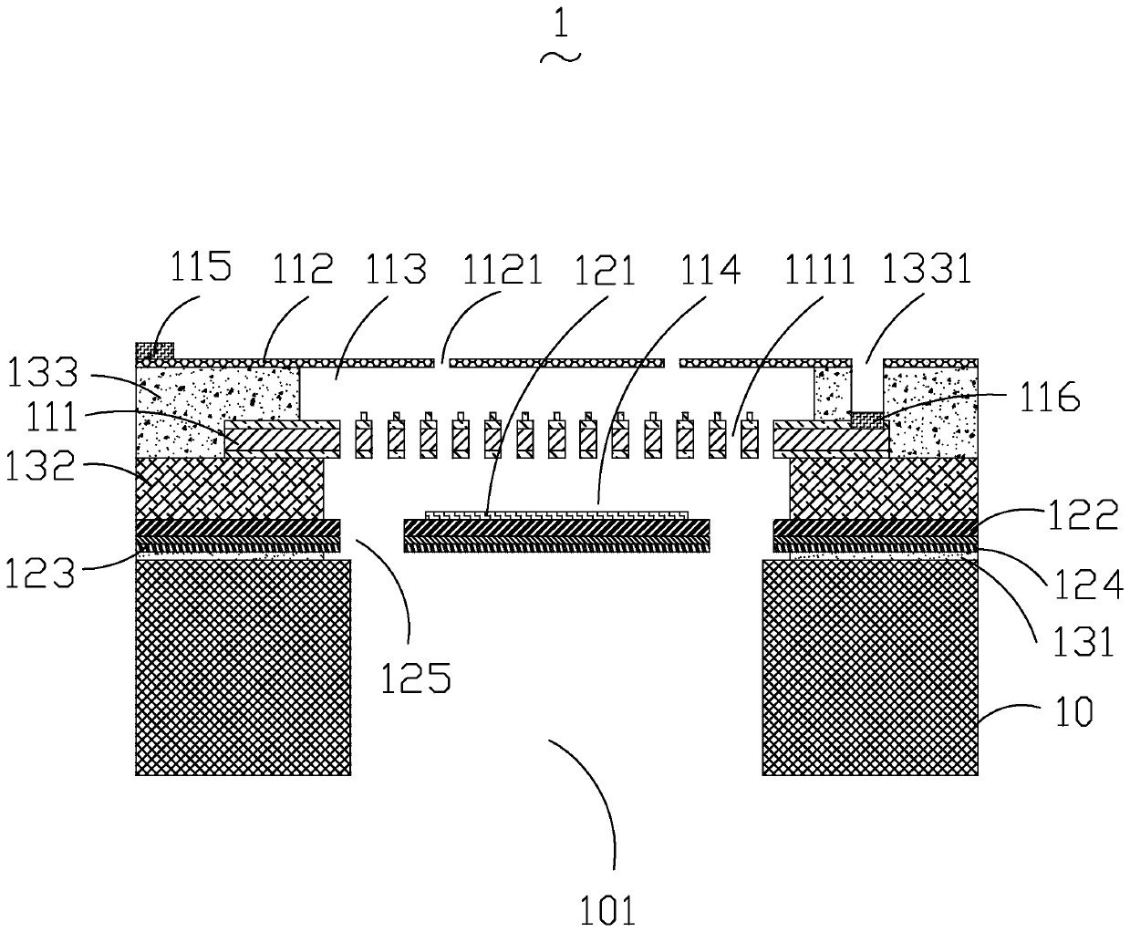
[0035] see figure 1 and figure 2 , the present embodiment provides a piezoelectric and capacitive MEMS microphone 1, including a base 10 and a capacitive system disposed on the base 10 and insulated and connected to the base 10, between the capacitive system and the base 10 A piezoelectric film structure 12 is also provided, a first insulating layer 131 is provided between the piezoelectric film structure 12 and the base, and a second insulating layer 132 is provided between the capacitor system and the piezoelectric film structure 12 .

[0036] The base 10 is made of semiconductor material and has a back cavity 101 , an upper surface and a lower surface opposite to the upper surface. The back cavity 101 runs through the upper surface and the lower surface. The back cavity 101 can be formed by bulk silicon micromachining or etching. The capacitive system is arranged on the piezoelectric film structure 12 through the second insulating layer 132, and the capacitive system incl...

Embodiment 2

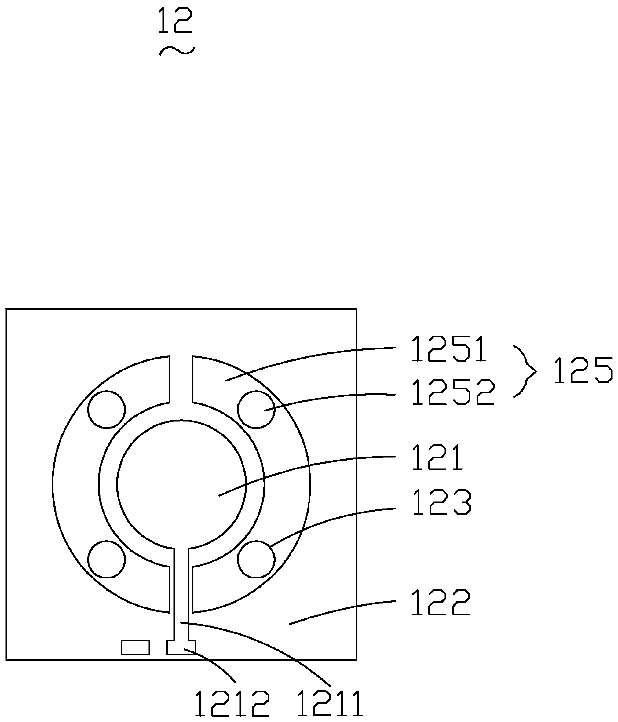
[0047] see image 3 and Figure 4 The difference between this embodiment and Embodiment 1 lies in the piezoelectric membrane structure 12. The piezoelectric membrane structure 12 of this embodiment is an edge-curved structure, which includes a first electrode sheet 121, a piezoelectric film laminated in sequence sheet 122, the second electrode sheet 123, the first electrode line 1211 and the first electrode terminal 1212, the center of the first electrode sheet 121, the center of the piezoelectric film 122 and the center of the second electrode sheet 123 are all on the same vertical line Above, the first electrode sheet 121 is compounded on the side of the piezoelectric film 122 facing the back plate 111, the first electrode sheet 121 is connected to the first electrode terminal 1212 through the first electrode wire 1211, and the second electrode 123 is compounded on the piezoelectric film One side of the sheet 122 facing the base 10, the two ends of the piezoelectric film 12...

Embodiment 3

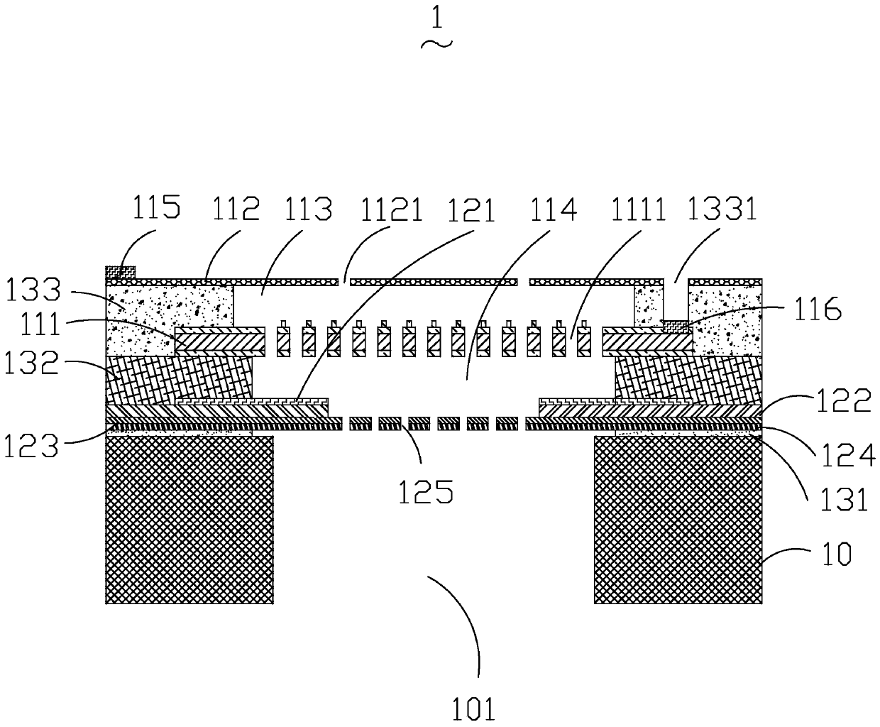
[0052] see Figure 5 and Figure 6 The difference between this embodiment and Embodiment 1 lies in the piezoelectric diaphragm structure 12. The piezoelectric diaphragm structure 12 in this embodiment is a four-cantilever beam structure, which includes a first electrode sheet 121, a pressing Electric diaphragm 122, second electrode sheet 123, first electrode wire 1211 and first electrode terminal 1212, the center of first electrode sheet 121, the center of piezoelectric diaphragm 122 and the center of second electrode sheet 123 are all on the same vertical line. On the straight line, the first electrode sheet 121 is compounded on the side of the piezoelectric film 122 facing the back plate 111, the first electrode sheet 121 is connected to the first electrode terminal 1212 through the first electrode wire 1211, and the second electrode 123 is compounded on the piezoelectric film 122. On the side of the electric diaphragm 122 facing the base 10, the piezoelectric diaphragm 122...


PUM


Abstract

The invention provides a piezoelectric type and capacitive type combined MEMS microphone. The MEMS microphone comprises a base with a back cavity and a capacitor system arranged on the base. The capacitor system comprises a backboard and a vibrating diaphragm. The back plate and the vibrating diaphragm are oppositely arranged at an interval to form a first sound cavity; a piezoelectric diaphragm structure is also arranged between the capacitor system and the base; a second sound cavity is formed between the capacitance system and the piezoelectric diaphragm structure; the second vocal cavity is at least communicated with the first vocal cavity or the back cavity, and the piezoelectric type and capacitive type combined MEMS microphone can output two groups of electric signals, including a group of electric signals output by a capacitive system and a group of electric signals output by a piezoelectric diaphragm structure, so that the sensitivity of the microphone can be improved.

Description

[0001] 【Technical field】 [0002] The invention relates to the technical field of acoustic-electric conversion devices, in particular to a MEMS microphone combined with a piezoelectric type and a capacitive type. [0003] 【Background technique】 [0004] MEMS microphone is an electro-acoustic transducer made by micromachining technology, which has the characteristics of small size, good frequency response characteristics, and low noise. With the miniaturization and thinning of electronic devices, MEMS microphones are more and more widely used in these devices. [0005] The MEMS microphone in the related art includes a silicon substrate and a plate capacitor composed of a diaphragm and a back plate, and the diaphragm is opposite to the back plate and separated by a certain distance. The diaphragm vibrates under the action of sound waves, causing the distance between the diaphragm and the back plate to change, resulting in a change in the capacitance of the plate capacitor, there...

Claims


Application Information

Patent Timeline
IPC IPC(8): H04R19/04
CPCH04R19/04H04R2201/003H04R17/02H04R23/02H04R7/06B81B3/0021B81B2201/0257B81B2203/0127B81B2203/0315B81B2203/04
Inventor 童贝占瞻李杨黎家健钟晓辉段炼
Owner AAC TECH NANJING
Why Eureka
Try Eureka