Combustion gas turbine low-emission combustion chamber and variable load air distribution adjusting method

A gas turbine and air distribution technology, applied in the direction of combustion methods, combustion chambers, continuous combustion chambers, etc., can solve the problems of reducing combustion air flow, increasing total pressure loss, etc., to achieve stable duty-level flames, improve stability, and reduce pollutants The effect of emissions

Active Publication Date: 2019-09-27
TONGJI UNIV
View PDF7 Cites 4 Cited by
  • Summary
  • Abstract
  • Description
  • Claims
  • Application Information

AI Technical Summary

Problems solved by technology

The advantage of this method is that it can greatly reduce the flow of combustion air, but its disadvantage is that the total pressure loss of the combustion chamber is greatly increased

Method used


Image

  • Combustion gas turbine low-emission combustion chamber and variable load air distribution adjusting method
  • Combustion gas turbine low-emission combustion chamber and variable load air distribution adjusting method
  • Combustion gas turbine low-emission combustion chamber and variable load air distribution adjusting method

Examples


Embodiment 1

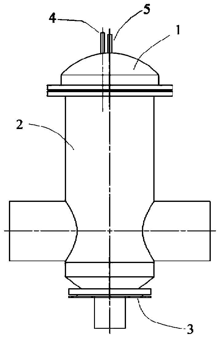
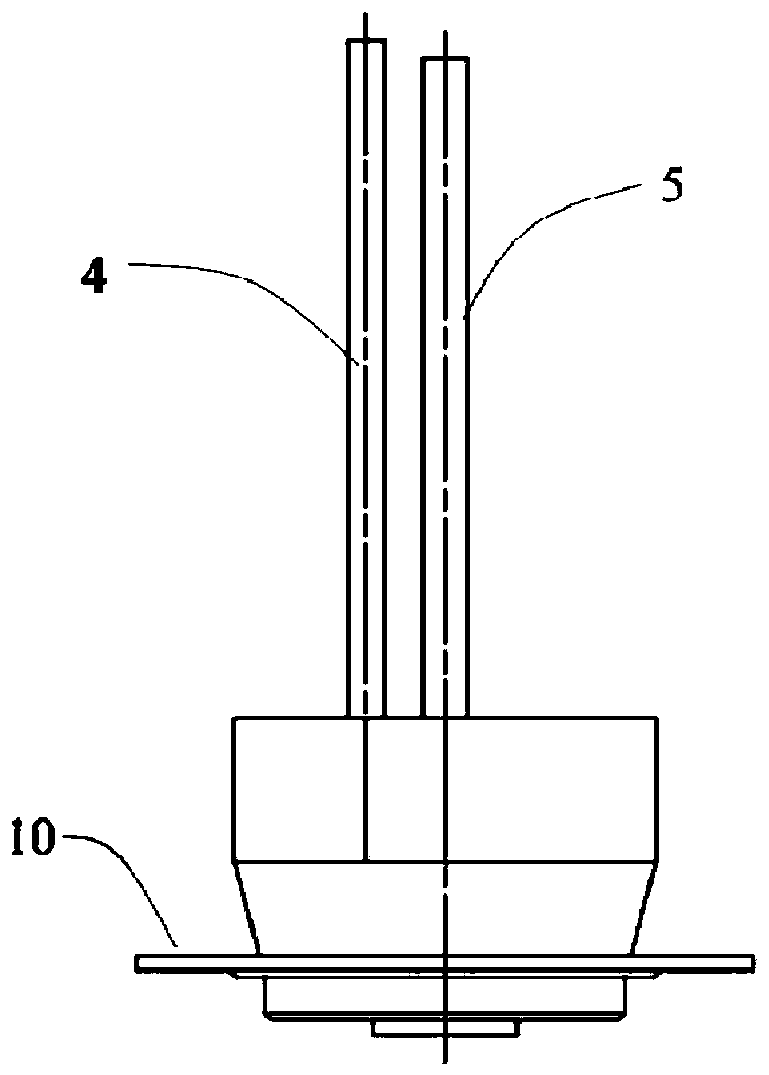
[0045] Such as Figure 1-9 As shown, a gas turbine low-emission combustor includes casing top cover 1, casing 2, combustor head (including main fuel level gas pipe 4, duty level gas pipe 5, premixing swirler 11, stabilizer Flame swirler 12, duty-level nozzle 13, main gas pressure stabilizing chamber 14, impingement cooling flame stabilizer 15, main combustion level gas flow equalizer 20 and head upper flange 10), flame tube 8, auxiliary positioning ring cone 6 and the tail baffle flange 3 of the flame tube.

[0046] The inside of the main fuel gas plenum 14 is a ring-column cavity, and the height of the cavity is not less than 4 times of its width. The outer wall of the main gas pressure stabilizing chamber 14 is connected to the premixing swirler 11, and the inner wall is connected to the flame stabilizing swirler 12, and the three are coaxially connected in series. The blades of the pre-mixing swirler 11 are straight blades, and the light transmission area of ​​the pre-mix...

Embodiment 2

[0058] A gas turbine low emission combustor such as Figure 1-9 As shown, the main components of the combustion chamber include: casing upper cover 1, casing 2, flame tube tail baffle flange 3, auxiliary positioning ring cone 6, flame tube 8, air regulating plate 7 and gas inlet pipe road including the combustion chamber head.

[0059] Such as figure 1 As shown, the top cover 1 of the casing, the casing 2 and the tail baffle flange 3 of the flame tube of the combustion chamber are connected up and down in sequence and arranged coaxially. A pair of air inlets 9 are arranged symmetrically near the rear of the casing 2 .

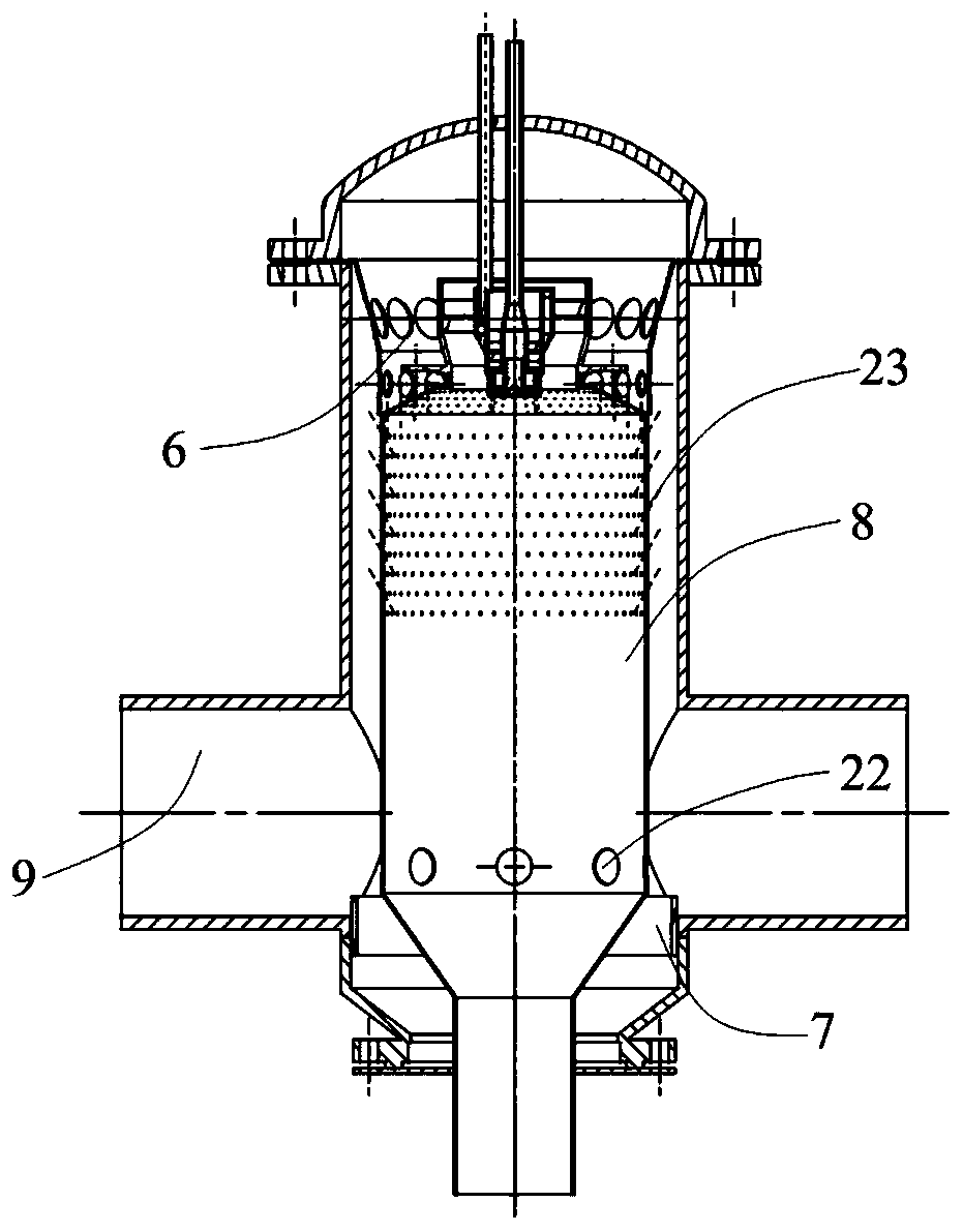
[0060] Such as figure 2 As shown, the auxiliary positioning ring cone 6, the flame tube 8, the air regulating plate 7 and the head of the combustion chamber are coaxially arranged. Wherein, the head of the combustion chamber and the flame tube 8 are connected up and down through the flange, and the flange part of the auxiliary positioning ring cone 6 is ar...

Embodiment 3

[0072] Such as figure 1 , figure 2A gas turbine low-emission combustor shown includes a casing 2, a casing top cover 1 arranged on the top of the casing 2, an air inlet 9 arranged on the side of the casing 2, and an air inlet 9 arranged inside the casing 2. The flame tube 8, the combustion chamber head arranged on the top of the flame tube 8 and the air distribution mechanism arranged on the side of the flame tube 8 and adapted to the air inlet 9.

[0073] The air distribution mechanism includes a mixing hole 22 provided on the side of the flame tube 8 and adapted to the air inlet 9, and an air regulating plate 7 that is arranged on the outside of the flame tube 8 and is compatible with the mixing hole 22. The plate 7 can reciprocate axially along the flame tube 8 . A wall surface cooling hole 23 is also opened on the side of the flame tube 8 , and the wall surface cooling hole 23 is located above the mixing hole 22 .

[0074] Such as image 3 , Figure 4 , Figure 5 As...


PUM


Abstract

The invention relates to a combustion gas turbine low-emission combustion chamber and a variable load air distribution adjusting method. The combustion chamber comprises a casing, a casing top cover arranged on the top of the casing, an air inlet formed in the side face of the casing, a flame tube arranged inside the casing, a combustion chamber head arranged at the top of the flame tube and an air distribution mechanism arranged on the side face of the flame tube and matched with the air inlet; and the position of an air adjusting plate relative to the a doping hole is adjusted to adapt to unit load changes. Compared with the prior art, the combustion gas turbine low-emission combustion chamber can significantly improve the circumferential uniformity of main combustion stage premixed gas in the combustion chamber head, stabilize the pressure fluctuation of the main combustion grade gas and stabilize an on-duty stage flame, so that the pollutant emission of the combustion chamber is reduced. By changing the position of the air adjusting plate at different loads, the air intake ratio of the combustion chamber head is adjusted, so that the wide load adaptability of the combustion chamber is improved, and the pressure loss caused by structural changes is reduced.

Description

technical field [0001] The invention belongs to the technical field of gas turbine combustion chambers, and relates to a low-emission combustion chamber structure suitable for using natural gas and other gases as fuels and an adjustment method for air distribution in the combustion chamber at different loads. Background technique [0002] The combustor is one of the three core components of a gas turbine. Its function is to convert the chemical energy of the fuel into thermal energy to drive the high-speed rotation of the turbine, and then convert it into mechanical work. As environmental protection policies require higher pollutant emission concentrations, the design and development of low-pollution combustors is becoming more and more important. [0003] At present, lean fuel premixing technology is an important way to reduce the emission of pollutants such as nitrogen oxides and carbon monoxide that has attracted the most attention from the industry. Reduce the average t...

Claims


Application Information

Patent Timeline
Patent Type & Authority Applications(China)
IPC IPC(8): F23R3/26F23R3/28F23R3/34
CPCF23R3/26F23R3/286F23R3/346
Inventor 宗超朱彤
Owner TONGJI UNIV
Why Eureka
Try Eureka