PDMS microlens array and method for preparing PDMS microlens array by liquid phase molding of concave mold

A technology of microlens array and concave mold, which is applied in the fields of lenses, instruments, optics, etc., can solve the problems of complex process, high cost, and difficult operation, and achieve the effect of simple process, easy operation, and low cost

Active Publication Date: 2021-02-23
UNIV OF ELECTRONICS SCI & TECH OF CHINA
View PDF4 Cites 0 Cited by
  • Summary
  • Abstract
  • Description
  • Claims
  • Application Information

AI Technical Summary

Problems solved by technology

[0006] The above-mentioned method for manufacturing the die is complex in process, difficult in operation, and high in cost

Method used


Image

  • PDMS microlens array and method for preparing PDMS microlens array by liquid phase molding of concave mold
  • PDMS microlens array and method for preparing PDMS microlens array by liquid phase molding of concave mold
  • PDMS microlens array and method for preparing PDMS microlens array by liquid phase molding of concave mold

Examples


Embodiment 1

[0072] The method for preparing the PDMS microlens array 160 by liquid phase forming of a concave mold comprises the following steps:

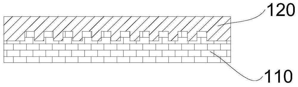
[0073] (1) Adopt SU-8 thick glue photolithography process to manufacture SU-8 photoresist cylinder structure array punch 110, the size of each cylinder is

[0074] (2) Mix 8 g of PDMS prepolymer and 0.8 g of curing agent, vibrate in an ultrasonic oscillator for 5 min to make the mixing more uniform, and vacuumize for 30 min to obtain a PDMS mixture.

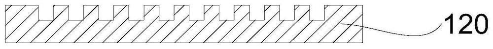
[0075] The PDMS mixture is evenly poured into the center of the cylindrical structure array punch 110, and the mold is placed on a horizontal plate to allow the PDMS mixture to flow and spread until it evenly covers the entire mold. After standing at 25° C. for 36 hours, the PDMS mixture is cured, and then the cured PDMS is peeled off from the mold to obtain a PDMS sheet 120 with a circular hole array.

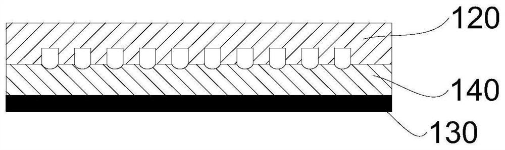
[0076] (3) Dip the silicon substrate 130 (18mm×18mm) into an acetone solution, clean it in...

experiment example 1

[0084] Figure 8 It is an optical micrograph of the SU-8 photoresist cylinder structure array convex mold manufactured in Example 1. It is observed from the pictures that the circular outlines of each cylindrical structure are of the same height, and the vertical and horizontal arrangement of the cylindrical structures is regular.

[0085] Figure 9 It is the optical micrograph of the SU-8 microlens array concave mold manufactured in embodiment 1. The bright area in the picture is the planar structure of the die surface, and the circular dark areas are the concave surface structure. The circular contours of each circular dark area have the same height, and the vertical and horizontal arrangement of the circular dark areas is neat and regular.

[0086] Utilize probe type surface profilometer (Veeco, Dektak150) to scan the surface of the SU-8 microlens array die prepared in embodiment 1, obtain the surface profile of a single die in the array die as follows Figure 10 shown....


PUM

PropertyMeasurementUnit
pore sizeaaaaaaaaaa

Abstract

The application provides a PDMS microlens array and a method for preparing the PDMS microlens array by liquid phase forming of a concave mold, which belong to the technical field of microlens array manufacturing. The method for preparing the PDMS microlens array by using the liquid phase molding of the concave mold includes: forming a liquid surface layer on the surface of the substrate, and the material of the liquid surface layer is a curable material. The surface of the opening side of the PDMS sheet with round holes distributed in an array is in contact with the liquid surface layer and maintained to solidify the liquid surface layer, so that the liquid surface layer forms a concave surface corresponding to the position of each round hole. The PDMS sheet and the cured liquid surface layer were peeled off to obtain a microlens array concave mold. The PDMS microlens array was fabricated from the concave mold of the microlens array. The concave mold of the microlens array is prepared by the method of liquid phase forming of the concave mold, the process is simple, the operation is easy, and the cost is low. The outer surface contour of the PDMS microlens array thus prepared has high molding quality and good imaging effect.

Description

technical field [0001] The present application relates to the technical field of microlens array manufacturing, in particular, to a PDMS microlens array and a method for preparing the PDMS microlens array by liquid phase molding of a concave mold. Background technique [0002] Soft lithography is a common method for fabricating PDMS microlens arrays. This method needs to manufacture the microlens array concave mold first, and then obtain the PDMS microlens array through PDMS soft lithography. Therefore, manufacturing the microlens array concave mold is a key step. [0003] The concave mold can be realized by photoresist hot-melt technology. Firstly, photolithography technology is used to form photoresist cylinder array microstructure on silicon wafer substrate, and then heated to above the glass transition temperature of photoresist. Due to the tendency of system energy minimization , the photoresist cylindrical structure is transformed into a hemispherical structure in a mo...

Claims


Application Information

Patent Timeline
Patent Type & Authority Patents(China)
IPC IPC(8): G02B3/00
CPCG02B3/0012G02B3/0018
Inventor 彭倍张遒姝王松徐锦涛
Owner UNIV OF ELECTRONICS SCI & TECH OF CHINA
Why Eureka
Try Eureka