
Radio frequency storage method and device based on microwave photon channelization

A radio frequency storage, microwave photonic technology, applied in the field of electronic spectrum reconnaissance and interference, can solve the problems of reducing processing bandwidth, limited working bandwidth, poor flexibility, etc., to achieve the effect of increasing working bandwidth and improving flexibility

Active Publication Date: 2019-09-27
NANJING UNIV OF AERONAUTICS & ASTRONAUTICS
View PDF4 Cites 9 Cited by
  • Summary
  • Abstract
  • Description
  • Claims
  • Application Information

AI Technical Summary

Problems solved by technology

The first is based on undersampling radio frequency storage technology, that is, to sample it at twice the highest frequency of the signal to reduce the requirements for A / D conversion, but due to the need to use the method of frequency ambiguity to restore The real signal makes its engineering implementation too difficult, especially the resolution of frequency ambiguity in the ultra-wide frequency band is even more difficult to achieve
The second is the radio frequency storage technology based on bilinear chirp transformation, that is, the wideband radar signal is converted into a narrowband signal through deskewing transformation, thereby reducing the processing bandwidth and meeting the requirements of the back-end hardware. However, due to the need to construct a chirp local oscillator source , requires the introduction of a priori reconnaissance reference information, so it puts forward high requirements for the accurate interception and measurement of radar signal modulation parameters, and this interference method can only be used for pulse compression radars using linear frequency modulation signals, and the application scenarios are limited
However, due to the limitation of the power in the ring, its storage time is limited, only in the order of μs, and it cannot realize complex signal modulation, reconstruction and retransmission, such as the Doppler frequency shift required for simulating a false dynamic target Modulation, etc., resulting in limited application space
[0007] It can be seen from the above that the current radio frequency storage technology based on electronic channelization stores, modulates, and reconstructs signals in the digital domain, so signal reconstruction has greater flexibility, but it requires the assistance of multiple sets of analog up and down conversion systems, resulting in Its working bandwidth is greatly limited, and the reconfigurability of the receiving system is poor; and based on photonic technology, it can only realize the storage function at present, without other necessary functions such as signal modulation, signal reconstruction and signal retransmission.
[0008] With the development of future radar systems in the direction of large bandwidth, multi-band, and reconfigurable, and the continuous improvement of radar anti-jamming technology and performance, the radio frequency storage technology in electronic jamming systems will face multiple challenges such as limited bandwidth and poor flexibility.

Method used


Image

  • Radio frequency storage method and device based on microwave photon channelization
  • Radio frequency storage method and device based on microwave photon channelization
  • Radio frequency storage method and device based on microwave photon channelization

Examples


Embodiment 1

[0060] Such as Figure 6 As shown, the multi-frequency optical local oscillator module used in this example is realized based on a mode-locked laser and an optical frequency comb generator. First, the mode-locked laser generates a set of repetition frequency f 1 , The optical frequency comb 1 with the number of comb teeth is N, as a signal optical frequency comb, assuming that the frequency of the first comb tooth is f 0 , then the frequency of the nth comb tooth is expressed as f 0 +(n-1)f 1 , (n=1,2...,N); Then inject the generated optical frequency comb 1 into the DFB (Distributed Feedback Laser, distributed feedback laser), at this time, the DFB laser is in a certain comb frequency with the optical frequency comb 1 The adjacent mode will be selected and output, and the signal of this mode will be used as the optical carrier, and sent to the optical frequency comb generator to generate another set of optical frequency combs 2, so as to realize the locking of the two opti...

Embodiment 2

[0065] The multi-frequency optical local oscillator module used in this embodiment is implemented based on two optical frequency comb generators. First, the single-frequency light generated by the laser is injected into the optical input end of the optical frequency comb modulator 1, and the frequency is f 1 The radio frequency signal is injected into the radio frequency input terminal of the optical frequency comb modulator 1, thereby generating a set of comb teeth with a number of N and a comb tooth interval of f 1 The optical frequency comb 1; Then the optical frequency comb 1 selects one of the comb teeth through the optical filter, injects it into the optical input end of the optical frequency comb generator 2, and realizes the mutual locking of the two optical frequency combs; the frequency is (f 1 +f m ) of the radio frequency signal is injected into the radio frequency end of the optical frequency comb generator 2, the optical frequency comb generator 2 output comb te...


PUM


Abstract

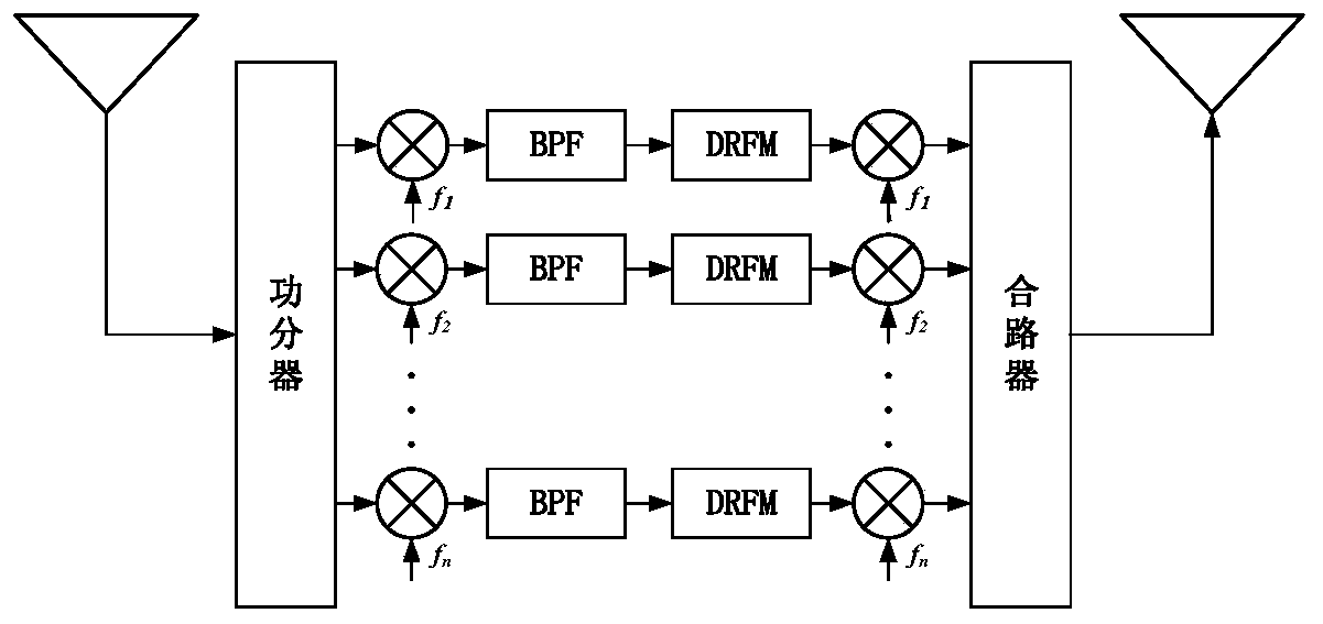
The invention discloses a radio frequency storage method based on microwave photon channelization. The method comprises the following steps: channelizing a reconnaissance broadband signal into a plurality of narrowband intermediate frequency signals; modulating a broadband radar signal carrier suppression single sideband into a first optical frequency comb signal with N comb teeth; dividing the first optical frequency comb modulation signal and the second optical frequency comb signal with N comb teeth into N independent channels according to the number of the comb teeth to be output, wherein the comb tooth intervals of the first optical frequency comb signal and the second optical frequency comb signal are f1 and (f1 + fm) respectively, and the first optical frequency comb modulation signal and the second optical frequency comb signal are mutually locked; and respectively carrying out photon mirror frequency rejection mixing on the nth output channel signal of the first optical frequency comb modulation signal and the nth output channel signal of the second optical frequency comb modulation signal, and converting the nth output channel signals into an intermediate frequency band to obtain an nth output channel channelized narrowband signal. The invention further discloses a radio frequency storage device based on microwave photon channelization. According to the invention, large-bandwidth, multi-band and reconfigurable radio frequency signal storage, reconstruction, modulation, forwarding and other functions can be realized.

Description

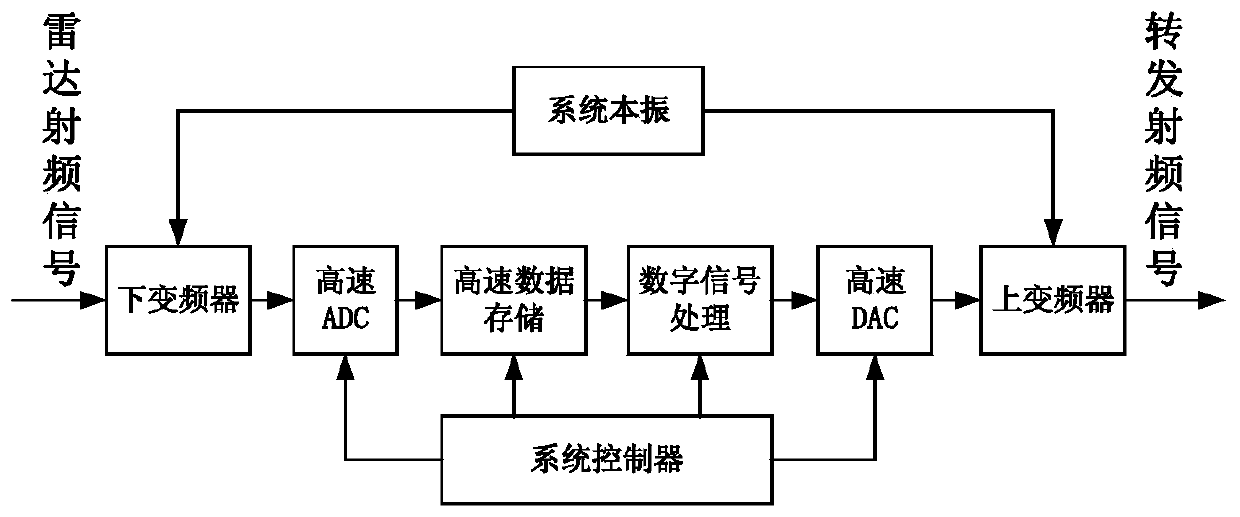
technical field [0001] The invention relates to the technical field of electronic spectrum reconnaissance and interference, in particular to a radio frequency storage method and device. Background technique [0002] As a key component of the electronic jamming system, radio frequency memory has the functions of storing, modulating, integrating and retransmitting radio frequency signals. It mainly reconstructs a jamming signal based on the intercepted broadband radio frequency signal to generate false targets to deceive or interfere with the other party. scouting system. A typical RF memory system such as figure 1 As shown, it mainly includes: down converter, analog-to-digital converter (ADC), memory, digital signal processing, digital-to-analog converter (DAC), up-converter and system controller. First, the intercepted broadband radio frequency signal is down-converted to the intermediate frequency band through the down-converter to meet the sampling requirements of the AD...

Claims


Application Information

Patent Timeline
Patent Type & Authority Applications(China)
IPC IPC(8): H04K3/00H04B10/2575H04B10/70G01S7/38
CPCG01S7/38H04B10/2575H04B10/70H04B2210/006H04K3/45
Inventor 朱丹陈文娟潘时龙潘明海周涛李益民钟欣陈智宇刘斯佳谢晨旭
Owner NANJING UNIV OF AERONAUTICS & ASTRONAUTICS
Learn More